FloBoss 407 Instruction Manual
3-24 Rev 5/00
3.4.15 RTD Input Module
The RTD input module monitors the temperature signal from a resistance temperature detector (RTD)
sensor or probe. The RTD module is isolated, reducing the possibility of lightning damage. A lightning
protection module (LPM) will not protect the RTD, but it helps protect the rack in which the module is
installed.
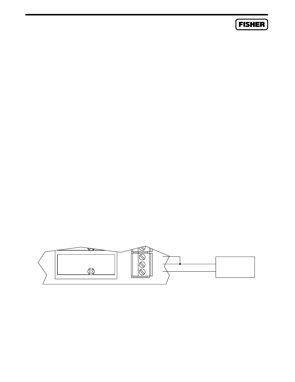
The RTD module needs to be calibrated while disconnected from the RTD probe; therefore, it may be
more convenient to perform calibration before connecting the field wiring. However, if the field wiring
between the ROC/FloBoss and the RTD probe is long enough to add a significant resistance, then
calibration should be performed in a manner that takes this into account.
3.4.15.1 Calibrating the RTD Module
The following instructions describe how to manually calibrate an RTD input channel for use with an
RTD probe having an alpha value of either 0.00385 or 0.00392 ohms/ohm/degree C. This procedure
requires a resistance decade box with 0.01 ohm steps and an accuracy of ±1%. You also need a
personal computer running the ROCLINK Configuration Software.
NOTE
For a more automated procedure, you may instead use the Calibrate pushbutton
associated with the Analog Input configuration, as described in Section 4 of the
ROCLINK user manual.
A4464821
1
ABC
DECADE BOX
RTD
WHTC
WHT
RED
B
A
Figure 3-21. Calibration Setup

 Loading...


