FloBoss 407 Instruction Manual
2-6 Rev 5/00
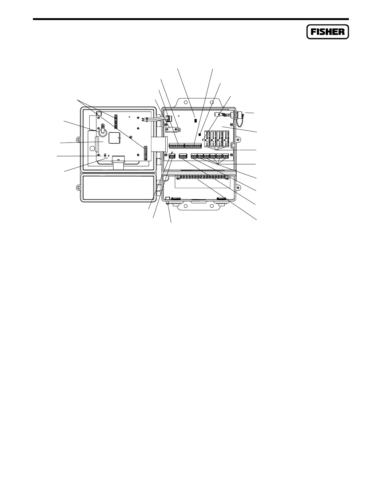
COMM BOARD
CONNECTORS
BACKUP
BATTERY
PROCESSOR
BOARD
RESET
STATUS
INDICATOR
+T POWER SUPPLY
JUMPER (P15 or W1)
OPERATOR INTERFACE PORT
PI STATUS INDICATOR
I/O MODULE CONNECTORS
I/O MODULE TERMINALS
AI/PI ON-BOARD I/O TERMINAL
AI ON-BOARD I/O TERMINAL
MVS PORT
EXTERNAL GROUNDING
TERMINAL
GROUND BUS BAR
POWER CONNECTOR
POWER INDICATOR
ROC407.wmf-mod
RJ11 BRACKET
COM1 (RS-232)
COM2 (COMM BOARD I/O)
AI/PI JUMPER (P4)
TERMINATION BOARD
LV START (S1)
Figure 2-1. Processor and Termination Boards
The processor board also has a 512 Kbyte flash memory chip for storing firmware such as the operating
system, factory code, user programs, and configuration parameters. A protected 64K block of flash
memory contains the operating system kernel (boot block). There are four different flash chips, which
determine the 407 version as follows:
♦
W68044 – Standard AGA92 Version 1.05 or greater (same part number as earlier FloBoss versions)
♦
W68073 – Standard AGA85 Version 1.05 or greater
♦
W68057 – Measurement Canada AGA92 Version 1.05 or greater
♦
W68074 – Measurement Canada AGA85 Version 1.05 or greater
Table 2-1 shows how the FloBoss 407 memory is allocated. Each memory location range (such as
00000 to 0FFFF) represents 64 Kbytes of memory.
A two-line LCD panel mounts on the display connector on the rear of the processor board. This
positions the display for viewing through the main door of the enclosure.

 Loading...


