FloBoss 407 Instruction Manual
Rev 5/00 2-7
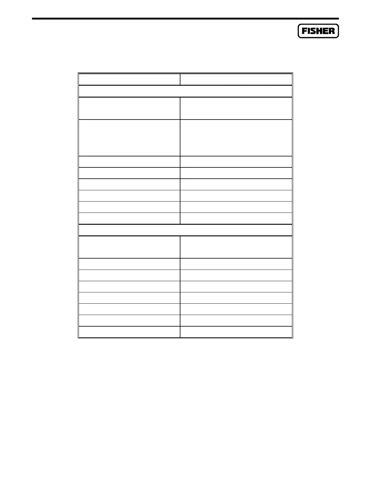
Table 2-1. FloBoss 407 Memory Map
MEMORY LOCATION USE
RAM
00000 to 003FF Interrupt Vectors
00400 to 0FFFF Boot Block Data
10000 to 1FFFF Events, Alarms, ROC Displays,
FST Data, Audit Log (Measure-
ment Canada version only), and
other Flash Program Data
20000 to 2FFFF Scratch Pad/Flash Program Buffer
30000 to 3FFFF History Data
40000 to 4FFFF History Data
50000 to 5FFFF History Data
60000 to 6FFFF User Program Data
70000 to 7FFFF User Program Data
FLASH MEMORY
80000 to 87FFF
88000 to 8FFFF
Configuration Save Area
Factory Program
90000 to 9FFFF Factory Program
A0000 to AFFFF User Program
B0000 to BFFFF User Program
C0000 to CFFFF User Program
D0000 to DFFFF Factory Code
E0000 to EFFFF Factory Code
F0000 to FFFFF Boot Block
A membrane keypad mounts on the main door of the enclosure and provides a local operator interface
with the FloBoss 407. A gasketed door mounted on the main door of the enclosure protects the keypad
from the elements. The keypad connects to the processor board with a ribbon cable.

 Loading...


