FloBoss 407 Instruction Manual
4-10 Rev 5/00
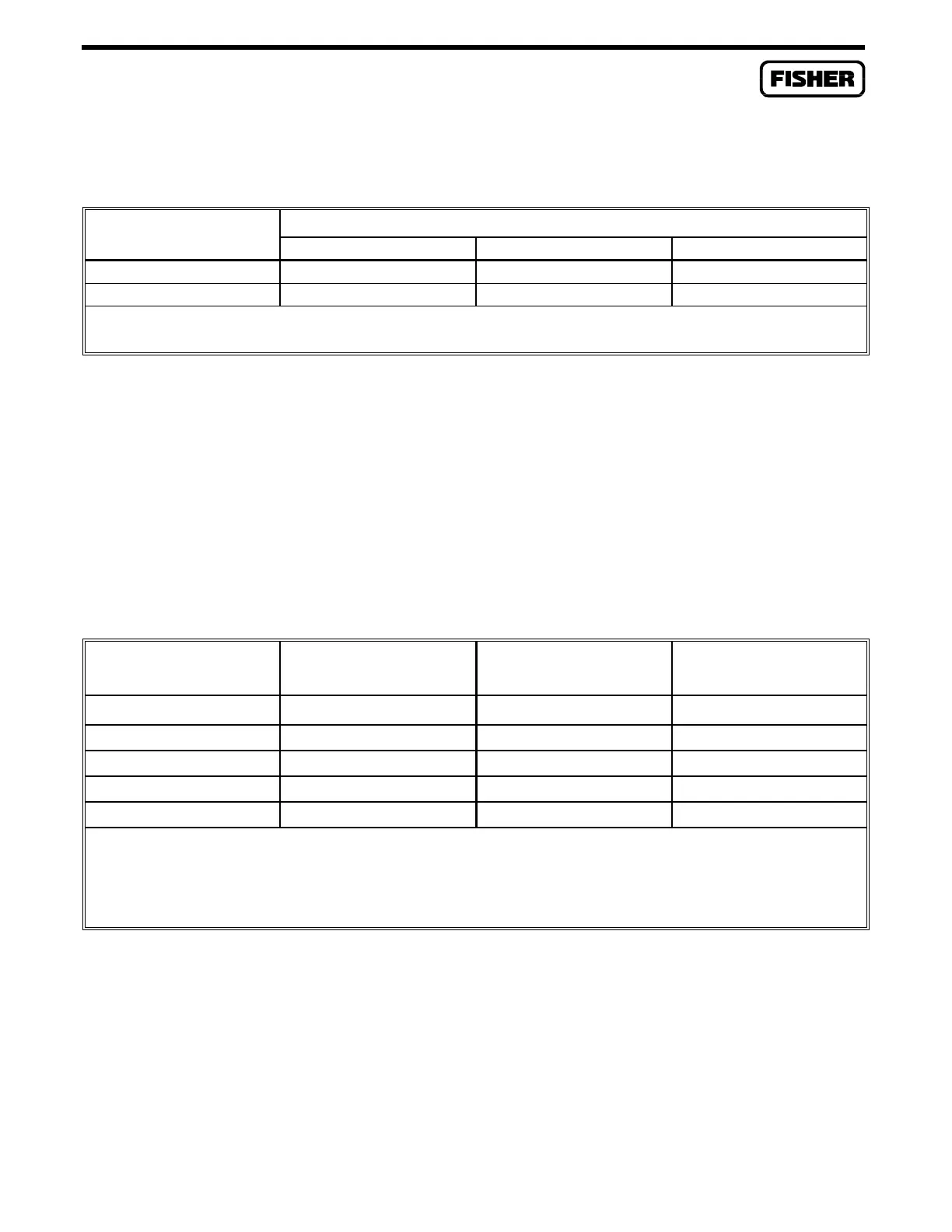
Table 4-2. Jumper Positions for the Leased-Line and Radio Modem Cards
MODE JUMPER POSITION
P3 P4 P5
2-Wire 2W 2W 2W
4-Wire 4W 4W 4W
NOTE: Jumper P6 on the Radio Modem Card is used to either ground (factory default) or isolate the push-to-
talk (PTT) return line.
4.3.3 Setting Attenuation Levels
For the leased-line and radio modem cards, the output level is set at the factory to 0 dB. This level can
be reduced, as necessary, to better match the modem output to the line or radio. The adjustment is
made by plugging a resistor into the card at the location labeled R2. Table 4-3 lists resistor values and
the amount of attenuation they provide.
Table 4-3. Leased-Line and Radio Modem Card Attenuation Levels
ATTENUATION
(dB)
R2 VALUE
(Ohms)
ATTENUATION
(dB)
R2 VALUE
(Ohms)
-2 205 K -12 15.8 K
-4 82.5 K -14 11.5 K
-6 47.5 K -16 8.66 K
-8 30.9 K -18 6.65 K
-10 21.5 K -20 5.11 K
NOTES: 1. All resistor values are nominal; 1% 1/4W resistors are acceptable.
2. Attenuation for leased or private-line operation or for a GE MCS radio is normally 0 dB;
in this case, no resistor is needed.
3. Attenuation for a GE TMX radio is typically -20 dB.
4. Attenuation for an MDS radio is typically -10 dB.

 Loading...


