FloBoss 407 Instruction Manual
Rev 5/00 4-5
C18
U7
Y2
U6
U5
1
2
30
P8
30
2
1
J2
U10
U9
R23
LEASED LINE/RADIO MODEM
C27
R24
R25
C26
CR6
Y1
RP1
RTS
RP2
C28
COM PORTS
C29
FB5
C25
C23
C24
C22
FB6
P7
3
5
7
1
R20
R16
R6
R15
R18
R19
R22
R21
C17
CR8
CR7
R17
30
2
1
P1
U3
U1
2W
2
C9
30
2
1
J1
FB3
FB2
FB4
C8
C6
C5
U4
CR1CR2CR3CR4CR5
TXDDCDCTS DTR RXD
C7
C11
C10
C13
C14
W1
C12
GND
4W
4W
2W
4W
2W
ISO
R10
R9
R12
R7
R8
R11
4
2
4
P6
C16
R14
R13
C15
P5
4
2
P4
4
2
C1
FB1
U2
R1
R2
C2
C4
P3
R26
R5
T2
T1
C19
U8
C20
C21
VR6
VR5
VR4
VR3
VR2
VR1
P2
1
DOC0247A
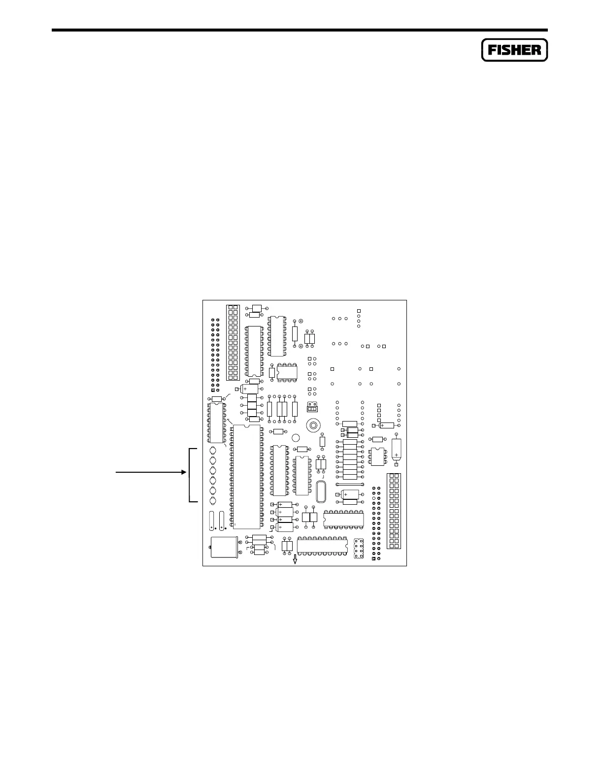
4.2.3 Radio Modem Communications Card
The Radio Modem Communications Card sends and receives full duplex or half-duplex, asynchronous
Frequency Shift Keyed (FSK) signals to the audio circuit of a two-way radio. The modem incorporates
a solid-state push-to-talk (PTT) switch for keying the radio transmitter. Refer to Figure 4-3.
LED indicators on the card show the status of the RXD, TXD, DTR, DCD, CTS, and RTS
control lines. LED indicators are detailed in Table 4-1.
There is one jumper (P6) which determines whether the PTT signal is isolated or grounded. Refer to
Section 4.4.3 for more information.
LED INDICATORS
Figure 4-3. Radio Modem Communications Card

 Loading...


