FloBoss 407 Instruction Manual
4-4 Rev 5/00
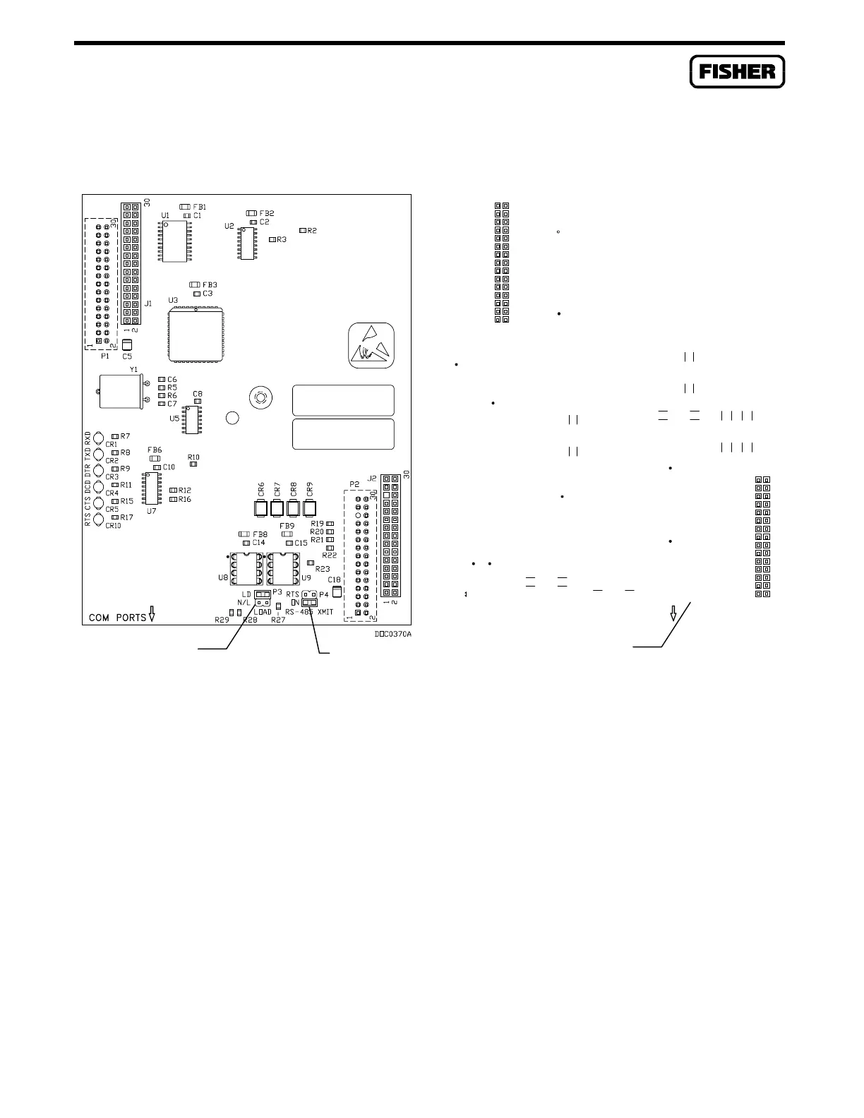
Figure 4-2. EIA-422/485 Serial Communications Card
The EIA-422/485 communications card includes LED indicators along the left-hand side that display
the status of the RXD, TXD, and RTS signal/control lines (the DTR, DCD, and CTS LEDs are unused).
LED indicators are detailed in Table 4-1.
The card has one jumper (P4 on the newer card; P3 on the older design) that applies to the EIA-422
transmit mode. The RTS setting of this jumper allows a multi-drop configuration. The newer card
design also includes load jumper (P3) that allows the termination load to remain or to be removed for
EIA-485 multi-drop communications. Refer to Section 4.4.2 for more information.
DOC023
C14
FB6
FB7
C16
U7
U8
RTS
ON
U4
U3
U5
RP2
RP1
Y1
C17
C18
CR3
DTR
CR6 CR5 CR4
CTSRTS DCD
CR2
RXD
CR1
TXD
COM PORTS
RS-485
C12
C2
U1
FB1
U2
C1
C3
C5
FB4
FB2
FB3
1
2
30
J1
30
2
1
P1
C4
CR10CR9CR8CR7
2
1
30
J2
RS-485
XMIT
P3
4
2
R8
R7
C15
R10
R9
1
2
30
P2
R5
R6
R4
R3
R1
R2
R11
R12
R13
RTS/ON Jumper
P3 for RS-422
RTS/ON Jumper
P4 for RS-422
Load Jumper P3
for RS-485
Newer Design Older Design
RS-485

 Loading...


