FloBoss 407 Instruction Manual
1-10 Rev 5/00
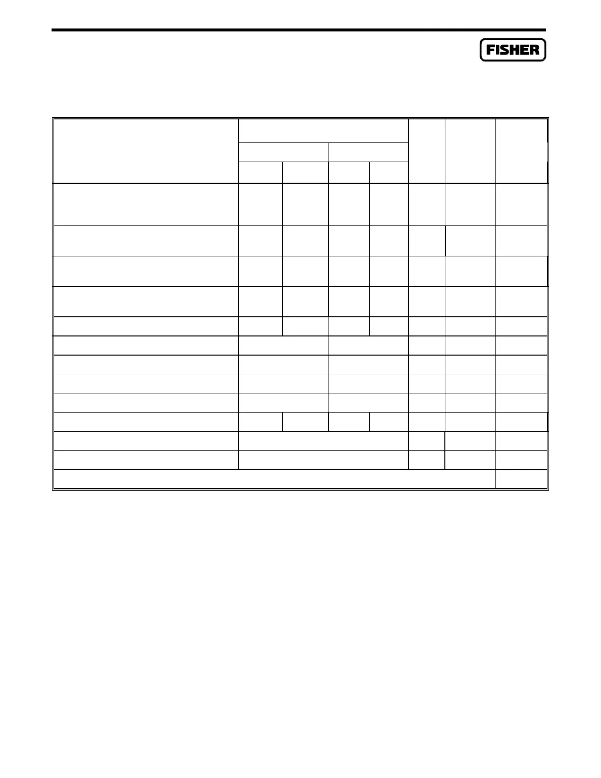
Table 1-1. Power Consumption of the FloBoss 407 and Powered Devices
POWER CONSUMPTION (mW)
DUTY SUB-
DEVICE 12V System 24V System QTY CYCLE TOTAL
P
min
P
max
P
min
P
max
(mW)
Processor and I/O Termination Board
(includes minimum built-in I/O power
consumption)
N/A 800 N/A 1200 1 N/A
Built-in Analog Input — ROC/FloBoss-
Powered Current Loop
130 440 130 440
Built-in Analog Input — Externally-
Powered Voltage Signal
0 65 0 275
Built-in Pulse Input — ROC/FloBoss-
Powered
012024
Built-in Pulse Input — Externally-Powered 0 0 0 0
Serial Communications Card 135 135 N/A
Dial-up Modem Communications Card 395 395 N/A
Leased-Line Communications Card 110 110 N/A
Radio Modem Communications Card 110 110 N/A
MVS (Integral or Remote) N/A 240 N/A 480 N/A
I/O Modules Total from Table 1-2 N/A N/A N/A
Radio (from Section 1.4.2) N/A N/A N/A
TOTAL
NOTE: 1. For the Analog Input, the Duty Cycle is the percent of time spent in the upper half of the operating range.

 Loading...


