FloBoss 407 Instruction Manual
Rev 5/00 3-13
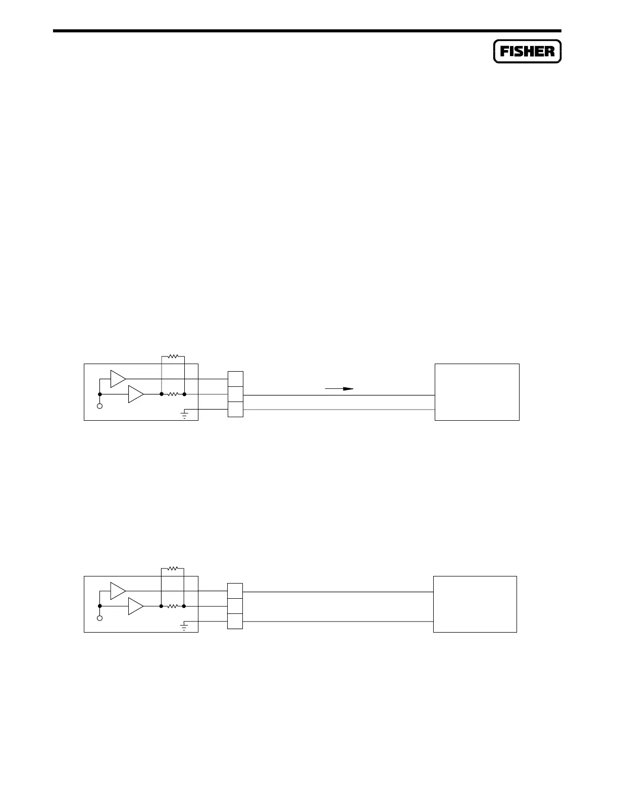
3.4.4 Analog Output Source Module
A schematic representation of the field wiring connections to the output circuit of the Analog Output
Source module is shown in Figure 3-9 and Figure 3-10. The AO Source module can provide either loop
current or output voltage to non-powered field devices. The Analog Output Source module provides
a 0- to 5.5-Volt output at terminal A, and a 0 to 30 milliamp current source output at terminal B.
Terminal C is referenced to the ROC/FloBoss common.
Resistor R1 (0-ohm resistor supplied) helps keep the loop resistance within the operating range of the
module. Remove the 0-ohm resistor when the loop resistance between terminals B and C is less than
100 ohms.
Terminals A and B are both active at the same time. Figure 3-9 shows wiring for a ROC/FloBoss-
powered current loop device, and Figure 3-10 shows wiring for an output voltage to non-powered field
devices.
R1=0
DOC0158A
(Modified)
LEVEL
220
AO SRC
I
REMOVE RESISTOR R1 WHEN LOOP
RESISTANCE IS LESS THAN 100 OHMS
I = 30 mA MAX
COM
+I
-
C
B
+
+V
A
ROC-POWERED
LOOP DEVICE
Figure 3-9. Analog Output Source Module Field Wiring for Current Loop Devices
V
R1=0
LEVEL
DOC0159A
AO SRC
220
V = OUTPUT VOLTAGE FROM MODULE = 0 TO 5 VDC, 5 mA
o
COM
+I
+V
+
C
B
-
o
A
VOLTAGE DEVICE
ROC-POWERED
Figure 3-10. Analog Output Source Module Field Wiring for Voltage Devices

 Loading...


