FloBoss 407 Instruction Manual
Rev 5/00 B-7
B.4 FIELD WIRING
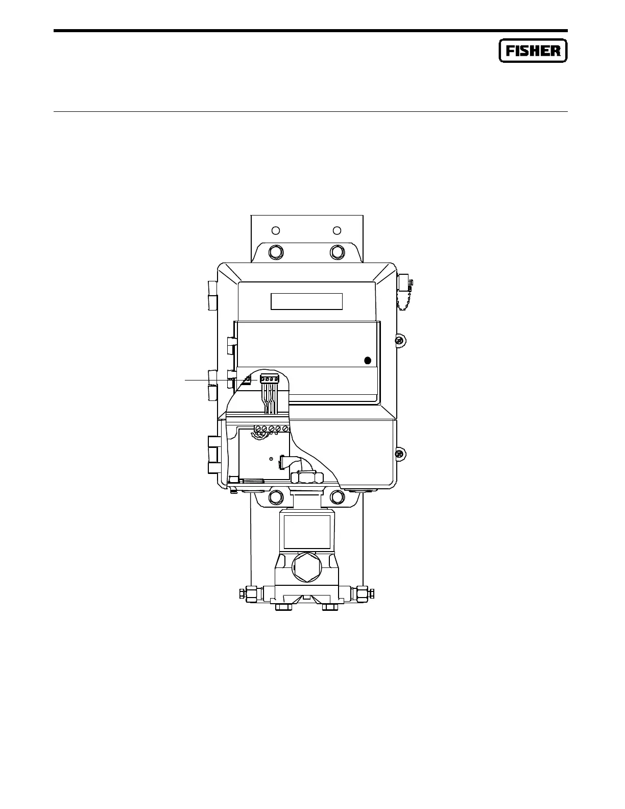
For an Integral MVS205, the FloBoss 407 and the Multi-Variable Sensor are shipped from the factory
with the wiring connected as shown in Figure B-8. The factory wiring uses yellow, blue, red, and black
wires (from left to right) in the MVS terminal block.
DOC0265A
Figure B-8. Signal Hook-Up for a Integral MVS205 Installation
In FloBoss 407 installations where there are one or more Remote MVS units, the signal wiring between
the FloBoss 407 and the Remote MVS is connected as follows. Use Sealtite
™
or a similar product to
provide a conduit path from the Remote MVS to the FloBoss 407. For explosion-proof installations, be
MVS
Terminal

 Loading...


