FloBoss 407 Instruction Manual
2-16 Rev 5/00
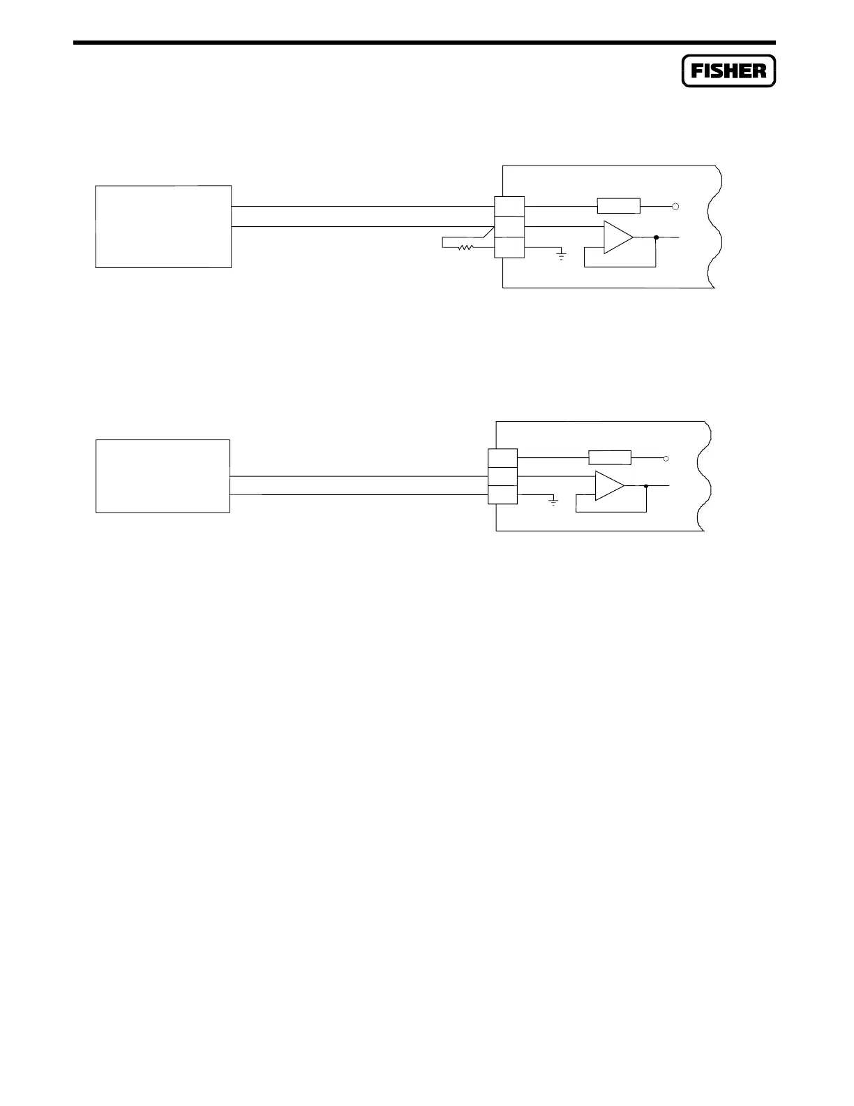
+
-
1 LIMIT
-
+
+T
+
-
ROC-POWERED
CURRENT LOOP
DEVICE
V
s
= 11 TO 30 VDC
+T = 24 VDC
+SIGNAL = 4 TO 20 mA
250 OHM
AI
V
s
DOC0098A
Modified
Figure 2-5. Current Signal on Built-in Analog Input
1 LIMIT
+
-
EXTERNAL/
SELF-POWERED
DEVICE
V
s
= 11 TO 30 VDC
+T = 24 VDC
+SIGNAL = 1 TO 5 VDC
AI
+T
+
-
V
s
DOC0098A
Modified
+
-
Figure 2-6. Voltage Signal on Built-in Analog Input
2.4.4 Built-in Pulse Input Wiring
Equipment Required: Flat-blade (1/8-inch width) screwdriver
Changing the P4 jumper to the “PI” position allows the built-in AI/PI input channel to be used as either
an isolated or a sourced pulse input. This pulse input signal is optically isolated from the FloBoss 407
circuit board. The pulse input can operate at up to 10 kHz, with a maximum 50% duty cycle.
The AI/PI channel has three field terminals. Terminal “+T” is a positive source voltage, either +24
volts or a level that follows the voltage of the FloBoss 407 input power. Terminal “+” is the positive
signal input; terminal “-” is the negative signal input. Be sure to remove the supplied 250-ohm resistor
from the terminal block when using the AI/PI channel as a pulse input.
To use the channel as an isolated input shown in Figure 2-7, connect the “+” and “-” field wires to
terminals “+” and “-” on the FloBoss 407 Pulse Input channel. When the field device sends a voltage
through terminal “+” on activation, the PI indicator LED on the termination board lights to show an
active circuit and the signal triggers the optical circuitry to signal the FloBoss 407.

 Loading...


