FloBoss 407 Instruction Manual
3-10 Rev 5/00
3.4.2 Analog Input Differential Module
A schematic representation of the field wiring connections to the input circuit of the Analog Input
Differential module is shown in Figure 3-4, Figure 3-5, and Figure 3-6.
The Analog Input Differential module measures either output voltage (V
o
)
or loop current (I) from
externally-powered devices only. The module operates by measuring the voltage between field wiring
terminals B and C. The module input is semi-isolated from the ROC/FloBoss power supply and signal
commons.
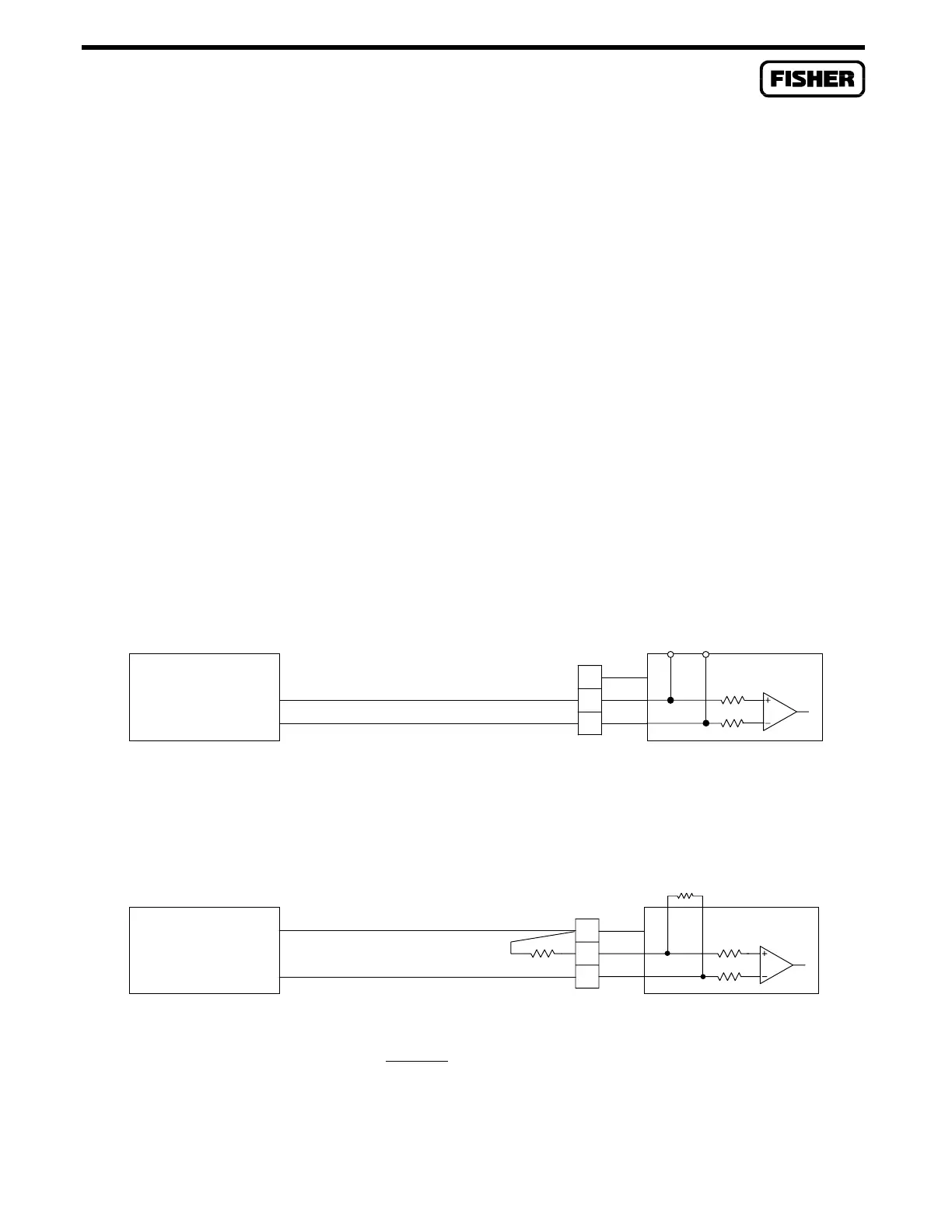
When connecting voltage devices, the 5-volts input voltage limit of the module must not be exceeded.
If the output of the field device is in the range of 0 to 5 volts dc, do not use a scaling resistor; ensure
that the supplied 250-ohm scaling resistor is removed. Refer to Figure 3-4 for connecting field devices
with outputs of 5 volts dc or less.
For field devices with output voltages that exceed 5 volts dc, two scaling resistors, R1 and R2, are
required (not supplied). Figure 3-5 shows how to connecting field devices with outputs exceeding 5
volts dc and where to install scaling resistors (at least 1%, 1/8W). The equation for determining values
of scaling resistors R1 and R2 is given in Figure 3-5. For example, if V
O
= 10 volts, and R1 = 250
ohms, then R2 = 250 ohms. Note that R1 must be less than 4.5K ohms.
V = VOLTAGE FROM ANALOG DEVICE = 0 TO 5 VDC
SELF-POWERED
ANALOG VOLTAGE
DEVICE
o
-
V
o
+
DOC0155A
N/C
C
-
B
A
+
200K
200K
R1 = OPEN
AI DIFF
Figure 3-4. AI Differential Module Field Wiring for Low Voltage Devices
V = VOLTAGE FROM ANALOG DEVICE = 5 TO 100 VDC
R1 MUST BE LESS THAN 4.5K OHM (1.0K OHM TYPICAL)
R1(V - 5)
TO SCALE R1 AND R2 FOR:
o
R2 =
o
5
DEVICE
ANALOG VOLTAGE
SELF-POWERED
-
o
V
+
DOC0156A
N/C
R2
C
B
+
-
A
R1
200K
200K
AI DIFF
Figure 3-5. AI Differential Module Field Wiring for Higher Voltage Devices

 Loading...


