FloBoss 407 Instruction Manual
Rev 5/00 3-27
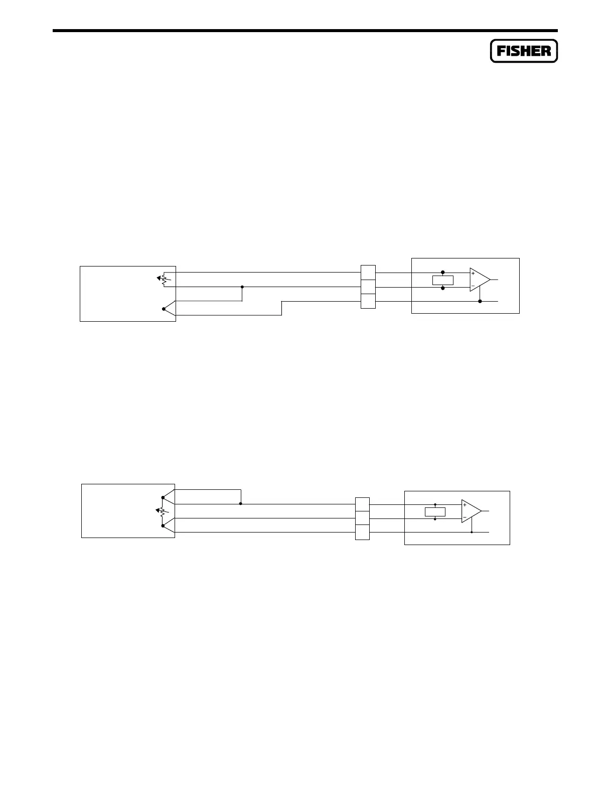
RTDs with 4 wires normally have the compensation loop separate from the active element loop to
increase the accuracy of the probe. Various colors are used for the probe wires. For example, some
probes have wire colors of red and white for the RTD element loop and black leads for the
compensation loop, while other probes use two red leads for the active element loop and two white
leads for the compensation loop.
The connections in Figure 3-24 connect a 4-wire RTD with compensation loop to the 3-wire RTD
module. The RTD module designed for 3-wire use does not permit a 4-wire RTD to provide any
additional accuracy over a 3-wire RTD.
RED
4-WIRE RTD
WITH COMPEN-
SATION LOOP
WHT
WHT
RED
WHT
C
RED
WHT
B
A
RTD
I SRC
DOC4008A
Figure 3-24. RTD Input Module Field Wiring for 4-Wire RTD With Compensation Loop
Figure 3-25 shows the connections for a single-element, 4-wire RTD. The two leads for one side of the
RTD are both red, and for the other side they are both white.
RED
4-WIRE RTD
WITH SINGLE
ELEMENT
WHT
WHT
RED
WHT
C
RED
WHT
B
A
RTD
I SRC
DOC4009A
Figure 3-25. Field Wiring for 4-Wire, Single Element RTD

 Loading...


