FloBoss 407 Instruction Manual
Rev 5/00 2-17
+T
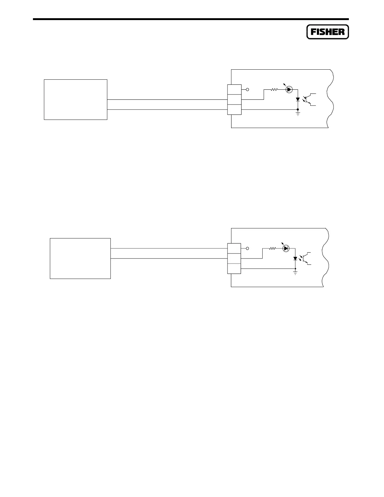
EXTERNALLY OR SELF
POWERED PULSE
DEVICE
-
+
-
+
AI/PI
+T
2.5K
DOC0209A
Figure 2-7. Externally-Powered Built-in Pulse Input
For use as a sourced input shown in Figure 2-8, connect the field device positive wire to terminal “+T”
and the field negative lead to terminal “+”. When the discrete field device conducts, the source power
flows through the LED to show an active circuit and triggers the optical circuitry to signal the FloBoss
407.
+T
ROC-POWERED
PULSE DEVICE
-
+
+T
AI/PI
2.5K
DOC0210A
-
+
Figure 2-8. FloBoss-Powered Built-in Pulse Input
2.4.5 Connecting Communications Wiring
Equipment Required: None
The FloBoss 407 has the flexibility to communicate to external devices using several different formats
and protocols. A special 3-pin connector provides a port for an operator interface device. Terminal
blocks located on the termination board provide connections to the COM1 and COM2 ports. Figure 2-9
shows the COM1, COM2, and Operator Interface port locations.
The Operator Interface port provides connections for a built-in EIA-232 communications interface to a
configuration and monitoring device. The configuration and monitoring device typically is a notebook-
style PC. A null modem cable (transmit and receive wires cross-connected, plus ground) must be used

 Loading...


