FloBoss 407 Instruction Manual
4-14 Rev 5/00
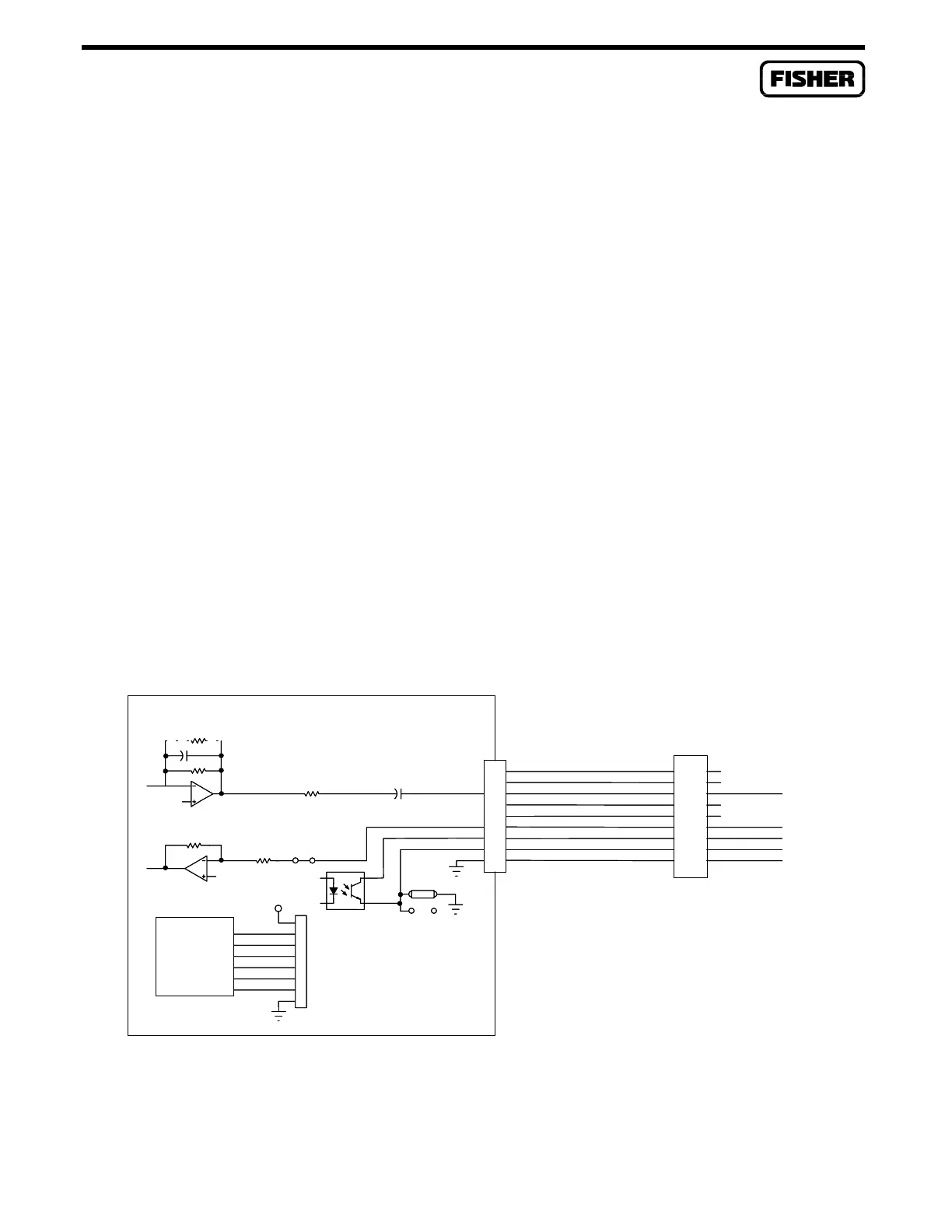
4.4.3 Radio Modem Communications Card Wiring
The following signal lines are used with most radios:
COM2
Terminal Signal Line Description
7 TXA Transmit data
5 RXA Receive data
4 PTT+ Push-to-talk switch
6 PTT- Push-to-talk return (may be grounded)
9 COM ROC/FloBoss power supply ground
The radio modem uses a jumper to determine the use of the PTT return line. The setting of this jumper
is described in Section 4.3.2.
The radio modem board is shipped without a resistor installed in the R2 position. To modify the
attenuation level, select a resistor as directed by Table 4-3 and insert it in the R2 position.
Figure 4-10 shows the relationship between the radio modem signals and terminal numbers for the
COM2 terminal block.
RADIO
DCD
INTERFACE
SHUTDOWN
DTR
RTS
8
2
3
5
6
TTL/RS232
RXD
TXD
1
7
4
P7
+5V
DCD
INTERFACE
SHUTDOWN
DTR
RTS
8
2
3
5
6
TTL/RS232
RXD
TXD
RECEIVE LEVEL
COM2
TERMINAL
BLOCK
6
9
5
4
7
TRANSMIT LEVEL
RECEIVE LEVEL
R10
RTS
W1
R2 OPEN
ISO
PTT
P6
GND
15
19
22
20
23
17
21
18
24
DOC0232A
Modified
PTT1
PTT2
PTT-
COM
PTT+
RXA
TXA
RXA
TXA
P8
RADIO MODEM CARD
Figure 4-10. Radio Modem Wiring Schematic

 Loading...


