Chapter 5: Installation
EST3X Technical Reference Manual 113
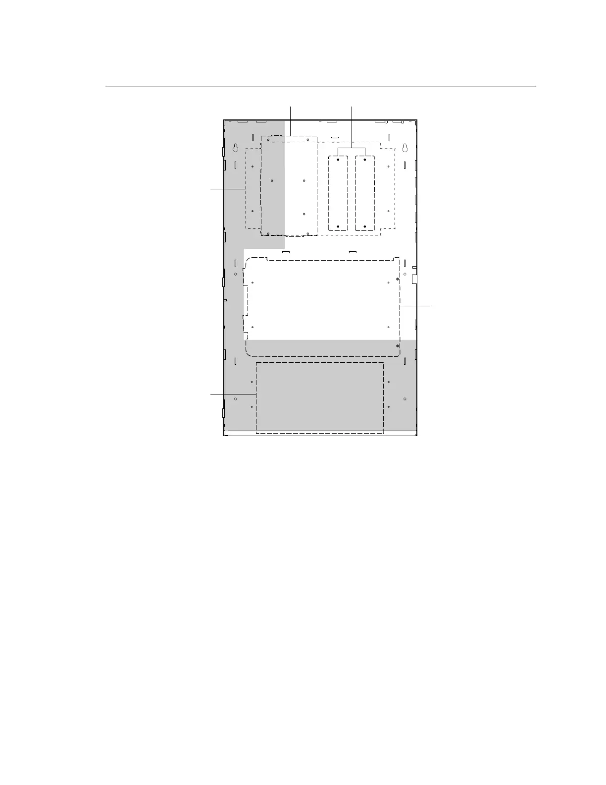
Figure 25: CAB6B backbox component footprints
(1) PS10-4B Power Supply Board mounting area
(2) Half-footprint module mounting areas
(3) 3X-PMI Paging Microphone Interface mounting area
(4) Standby battery compartment area
(5) SFS1-ELEC Chassis Electronics Assembly mounting area
Note: Route nonpower-limited wiring on the shaded area of the cabinet and power-limited wiring
on the non-shaded area.