Appendix A: System calculations
EST3X Technical Reference Manual 235
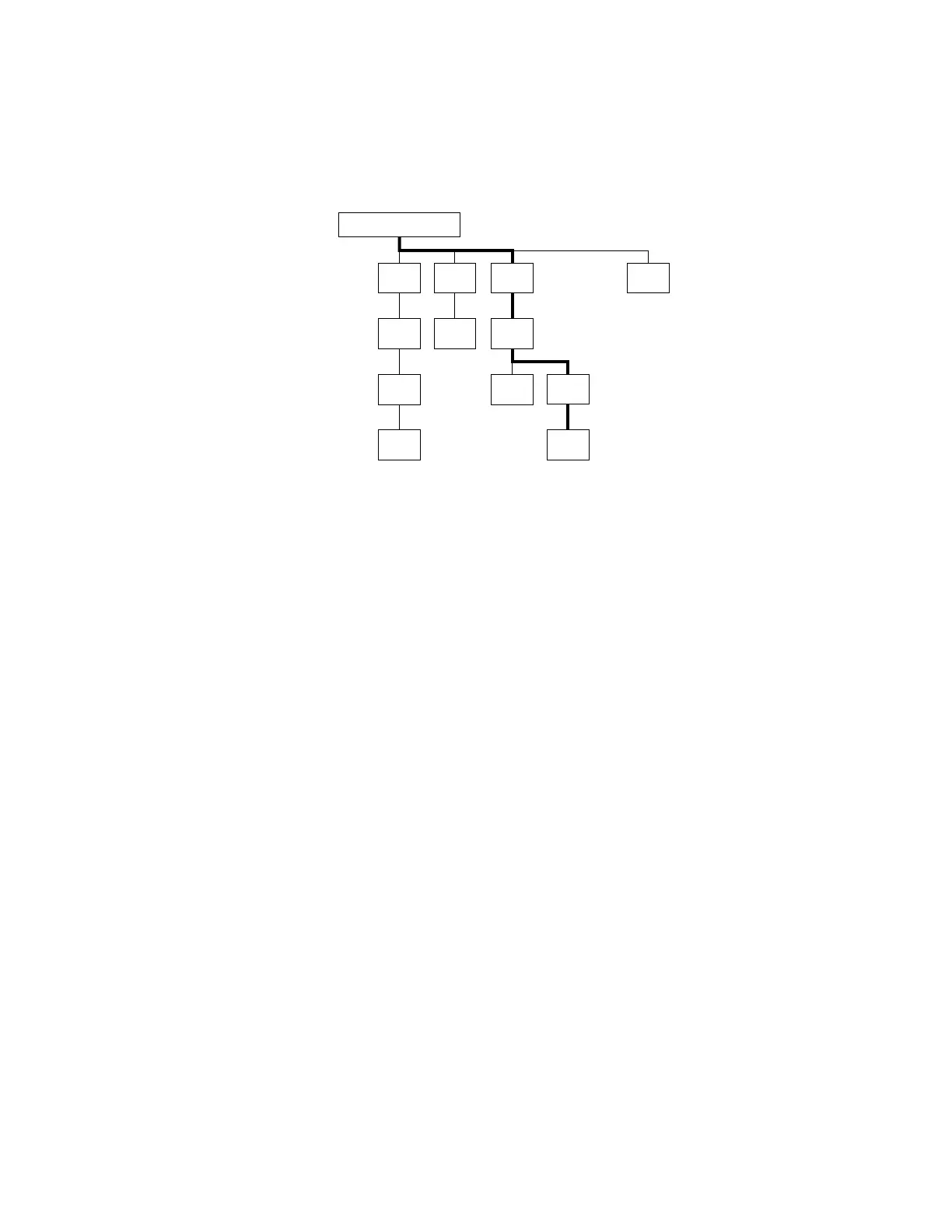
Determine the maximum allowable branch length
The maximum branch length is the wire distance measured from the Signature
controller module to the last device on the longest loop path as shown below.
(1) Signature loop controller
Several factors influence the maximum allowable branch length:
• Wire gauge and type
• Number of Signature detectors and modules installed on the branch
• Number of SIGA-UMs or SIGA-MABs configured for two-wire smoke
detectors installed on the branch
Table 72 through Table 75 provide the maximum allowable branch length for any
detector, module, SIGA-UM, and SIGA-MAB and the wire gauge combination.
Using the wire distances specified in the tables ensures that the signaling line
circuit does not exceed the maximum circuit resistance of the Signature loop.
Note: To calculate the wire distance with respect to circuit resistance, the tables
assume that the loop is end-loaded (all devices are clustered more towards the
end of the loop) and the loop uses standard non-shielded wire.
To determine the maximum allowable length of a Signature data loop
branch:
1. Identify the device located farthest from the Signature controller.
2. Determine the number of Signature detectors, modules, and SIGA-UMs or
SIGA-MABs configured for two-wire smokes that lie on the same conductive
path between the device identified in step 1 and the Signature controller.
3. Calculate the number of detector and module addresses. Some Signature
modules require two addresses.
4. Determine the size of the wire used to construct the loop.