Chapter 5: Installation
138 EST3X Technical Reference Manual
3. Set the printer DIP switches as shown in Table 27 or Table 28.
4. Replace the DIP switch cover.
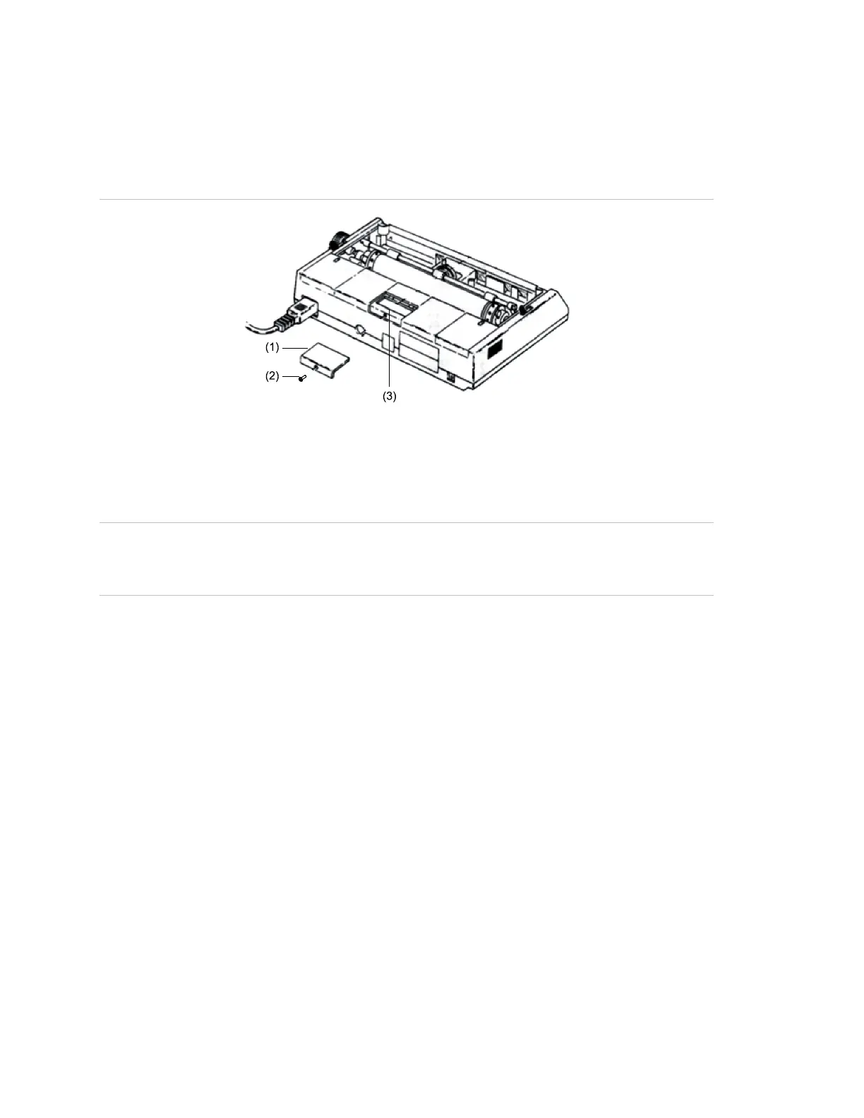
Figure 35: Removing the PT-1S printer DIP switch cover
(2) DIP switch cover screw
Wiring
WARNING: Electrocution hazard. To avoid personal injury or death from
electrocution, remove all sources of power and allow stored energy to discharge
before installing or removing equipment.
Notes
• Use a serial cable with a 25 pin, D-Sub male connector on one end. The
cable can be purchased locally or constructed using the DB-25 connector
provided with the printer.
• Serial printer connections are power-limited and may or not be supervised,
depending on the control panel.
• Locate supervised serial/USB printers in the same room as the equipment to
which they connect.
• Locate unsupervised serial/USB printers in the same room and within 20 ft.
(6.1 m) of the equipment to which they connect. Enclose wiring in conduit or
equivalent protection against mechanical injury.
• Serial connection requires UL Listed and CSA Approved shielded RS-232C
cable. Cable length may not exceed 50 ft. (15.2 m).