Chapter 5: Installation
EST3X Technical Reference Manual 145
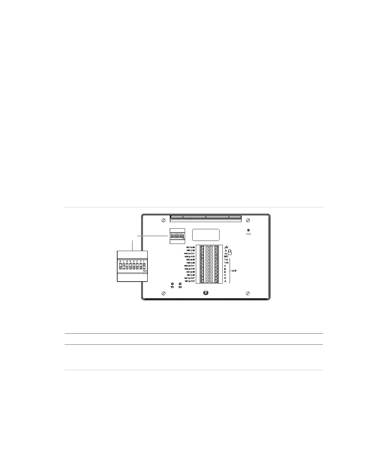
R-Series annunciator DIP switch settings
For correct operation, the R-Series remote annunciator must be configured with a
unique address and must be in communication with the EST3X fire alarm control
panel. These settings are configured from the DIP Switch SW1 on the back of the
annunciator (see Figure 41). Refer to Table 31 for descriptions of each Switch
SW1 segment (switch). Refer to Table 32 on page 146 for examples of address
settings.
For complete R-Series annunciator installation instructions, see the R-Series
Remote Annunciators and Expanders Installation and Operation Guide
(P/N 3100969-EN).
Note: DIP Switch SW1 segment 7 (SW1-7) must be set to On for annunciator
communication with the EST3X fire alarm control panel. In the On position,
R-Series remote annunciators and GCI graph annunciators support Class B and
Class A wiring, Style 6.
Figure 41: R-Series annunciator rear view showing DIP SW1 segments
(1) DIP Switch SW1
Table 31: DIP Switch SW1 settings
Description
W1-1 to SW1-5 Annunciator address (in binary):
The factory preset address is 2. Possible values are 1 to 31. See
Table 32 for examples.
W1-6 Baud rate:
Off = 9600 baud (factory default setting)
On = All other baud rates