Chapter 2: Product description
18 EST3X Technical Reference Manual
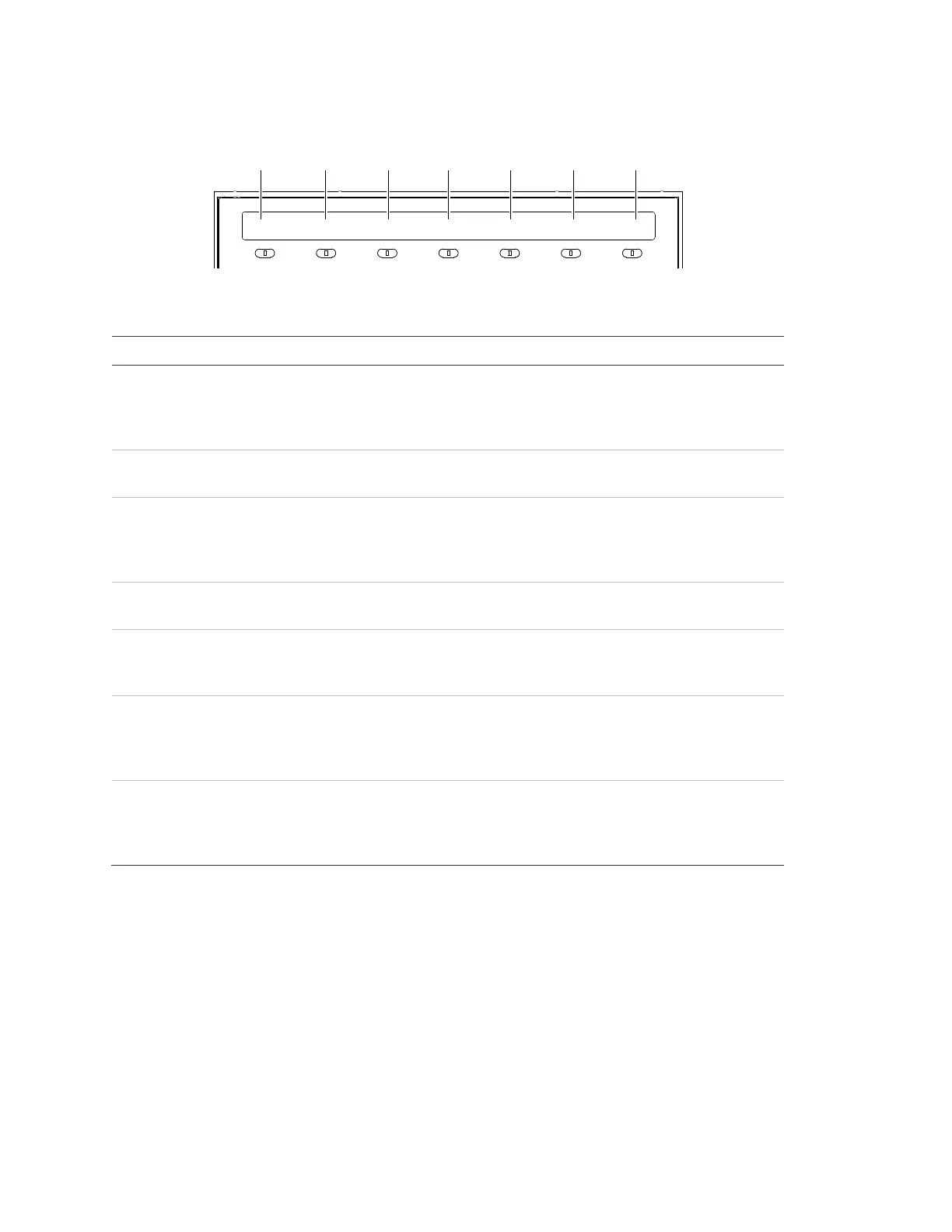
System status indicators
ALARM DISABLE SUP GND FAULT CPU FAIL TROUBLE POWER
(1) (2) (3) (4) (5) (6) (7)
Table 6: User interface system status indicator descriptions
Indicator Description
Alarm The LED serves as a common alarm event indicator. A flashing
LED indicates that there is an event in the Alarm Queue that ha
not been acknowledged. A steady LED indicates that all events
in the queue have been acknowledged.
Disable The LED indicates that a device, card, group, time control,
switch, or LED has been manually disabled.
SUP The LED serves as a common supervisory event indicator. A
flashing LED indicates that there is an event in the Supervisory
Queue that has not been acknowledged. A steady LED indicat
that all events in the queue have been acknowledged.
GND Fault The LED indicates that the SFS1-CPU module has detected a
ground fault.
CPU Fail The LED indicates that the CPU has detected a processor
failure. Processor failures must be reset manually using the
Reset button.
Trouble The LED
serves as a common trouble event indicator. A flashing
LED indicates that there is an event in the Trouble Queue that
has not been acknowledged. A steady LED indicates that all
events in the queue have been acknowledged.
Power The LED indicates the primary (AC) power status. The LED
when the panel has primary power. The LED is off when the
panel does not have primary power or when part of a life safety
network another panel does not have primary power.
LCD screen indications
The LCD screen on the user interface provides information relevant to the current
functional condition of the control panel. There are two screen modes: system
normal and system off-normal.