Chapter 5: Installation
122 EST3X Technical Reference Manual
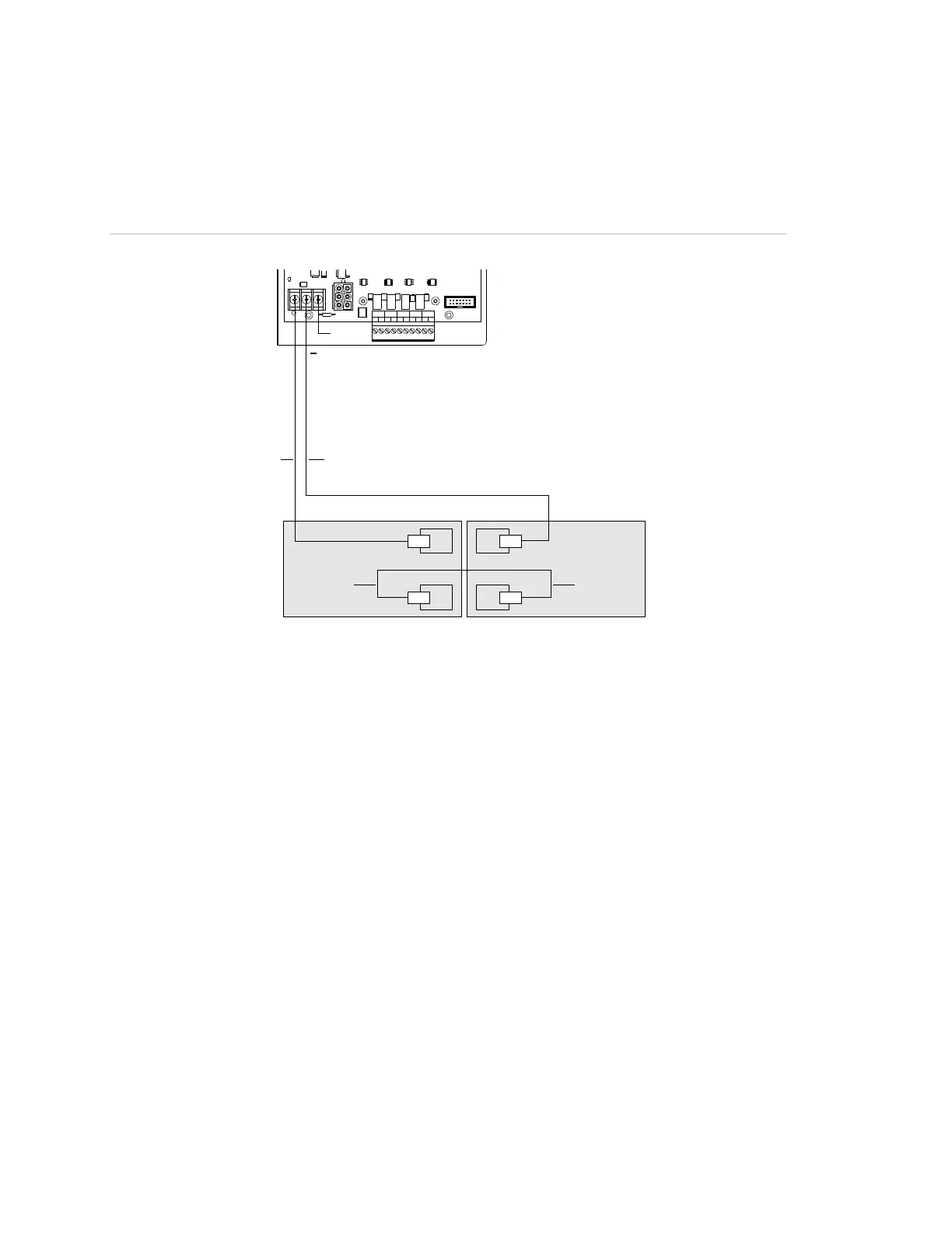
Use the diagram in Figure 30 when connecting the battery wiring to the power
supply. Before connecting the batteries, confirm the panel is already powered up
using AC power.
Figure 30: Wiring standby batteries to the power supply
TB3
+
+
−
−
+
J5
TB2
TB3
J2
+
-
+
-
+
-
+
-
+
-
NAC AUX 1 NAC AUX 2 NAC AUX 3 NAC AUX 4
N. C.
PS10-4B
(1)
(2)(4)
(3) (3)
(1) No connection
(2) Black wire from standby battery
(3) Blue wire
(4) Red wire from standby battery
Connecting auxiliary/booster power supplies
UL requires that you monitor secondary power sources housed in auxiliary and
booster power supply enclosures for loss of AC power to ensure the following:
• Upon loss of AC power, the control panel must provide an audible and visible
trouble signal
• Remote station, central station, and proprietary-type protected premises units
must transmit a trouble signal off-premises
To meet UL requirements, you need to connect a SIGA-CC1 (or SIGA-CC1S)
and a SIGA-CT1 to the booster supply. The SIGA-CC1 is used to activate the
booster supply and to signal common troubles. The SIGA-CT1 is used to signal
booster supply AC power failures.
Mount the SIGA-CC1 and SIGA-CT1 inside the booster supply cabinet as
described in the technical documentation received with booster supply. Connect
field wiring as shown in Figure 31 on page 124.