Chapter 5: Installation
EST3X Technical Reference Manual 121
Note: Model MN-PASM was replaced by model MN-PASM2. For systems still
using an MN-PASM, refer to the MN-PASM Preamp Supervision Module
Installation Sheet (P/N 3101580).
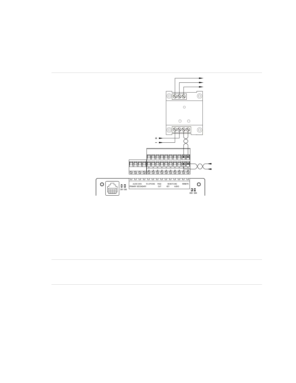
Figure 29: MN-PASM2 wiring for an audio subsystem
8 7 6
MN-PASM2
4 3 2 1
3-ASU
(2)
(3)
(1)
NO
C
NC
(1) Trouble relay. Normally closed contact (NC) held open. Normally open contact (NO) held
closed. Unsupervised and power-limited.
(2) Line level audio in. Supervised and power-limited. Replace the 3-ASU terminal block with the
terminal blocks supplied with the MN-PASM2.
(3) Supervised and power-limited. Use the control panel power supply or a 24 VDC, continuous,
regulated, power supply that is UL/ULC Listed for fire protective signaling systems.
Standby batteries
Caution: To avoid damage to equipment, do not connect standby batteries
unless the control panel is already powered up using AC power. See “Initial
power up” on page 43.
To provide continued panel operation in the event mains power is interrupted, the
24 VDC rechargeable battery circuit on the PS10-4B Power Supply has the
capacity to charge up to two 65 Ah sealed lead acid standby batteries.
Up to two 17 Ah sealed lead acid standby batteries can be housed on the battery
tray in the CAB6B backbox (see Figure 25 on page 113 for the compartment
location). Install batteries larger than 17 Ah in a separate listed enclosure.