Chapter 5: Installation
EST3X Technical Reference Manual 125
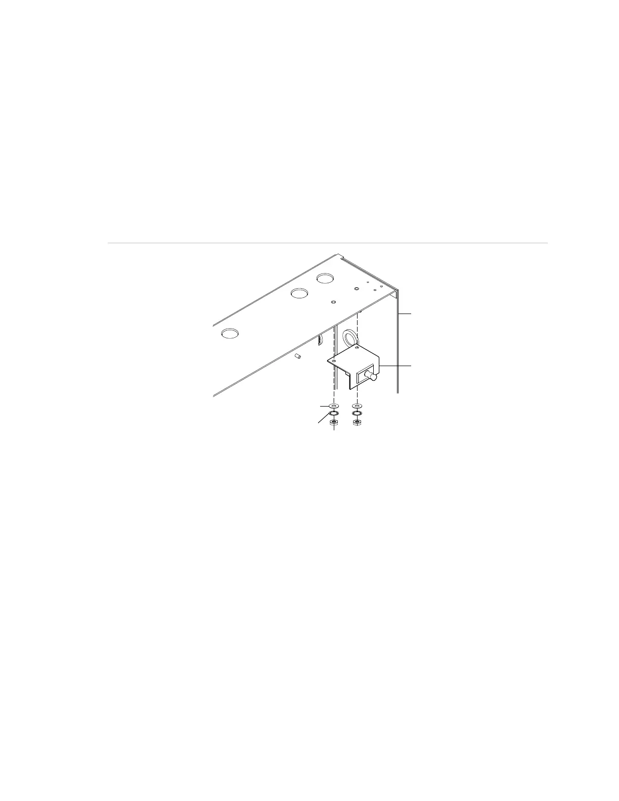
Tamper switch
It is a UL Listing requirement that all control panels in a life safety system that
includes security functions have a tamper switch. When the EST3X control panel
is integrated with an EST3 network, install a 3-TAMP supervision switch to meet
UL requirements. Figure 32 shows the mounting location in the CAB6B.
Before installing the switch, refer to the 3-TAMP, 3-TAMP5, 3-TAMPRCC
Cabinet Tamper Switches Installation Sheet (P/N 387422) for additional
installation information and wiring instructions.
Figure 32: Installing the 3-TAMP tamper switch in the CAB6B
(1) #8 flat washer (2X)
(2) #8 lock washer (2X)
(3) #8-32 nut (2X)
Fiber optics
3X series fiber network option modules provide a fiber optic or combination fiber
optic and RS-485 communication path for up to 64 control panels on EST3X and
EST3X/EST3 combination networks.
EST3X network
For an EST3X network, the 3X-FIB8 and 3X-FIB fiber network option modules
are available, both providing fiber optic or combination fiber optic and RS-485
communication.
• 3X-FIB8 Fiber Network Option Module: Provides a communication path for up
to eight EST3X control panels on an EST3X network. Refer to the 3X-FIB8
Fiber Network Option Module Installation Sheet (P/N 3101769) for installation,
wiring, and specifications.