Chapter 5: Installation
124 EST3X Technical Reference Manual
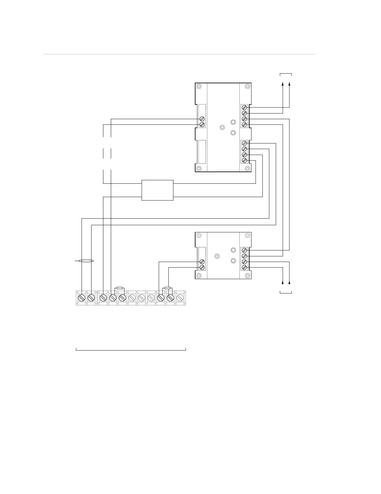
Figure 31: Typical booster power supply wiring
7
8
1
2
3
4
IN
IN
COM
OUT
COM
O
UT
Sense
1
Sense
2
NO
COM
NC
+
−
200 mA AUX
47 EOLR
P/N EOL-47
k Ω
+
−
−
+
+
−
+
−
12
3
4
56
7
8
9
10
N.
O
.
C
.
0
V
2
4
P
AM-
1
SIG
A-C
T1 S
IGA
-CC1
47 EOLR
P/N EOL-47
k Ω
(10)
(1)
(2)
(3)
(4)
(5)
(6)
(7)
(8)
(9)
(11)
(1) Auxiliary/booster supply
(
2) Not supervised
3) Normal
4) Active
5) Blue
(8) Red
(9) Install a PAM-1 or equivalent listed relay only when
required to supervise the 200 mA AUX circuit wiring
(10) Data Out, Signature loop to next device
(11) Data In, Signature loop from previous device