Chapter 5: Installation
EST3X Technical Reference Manual 117
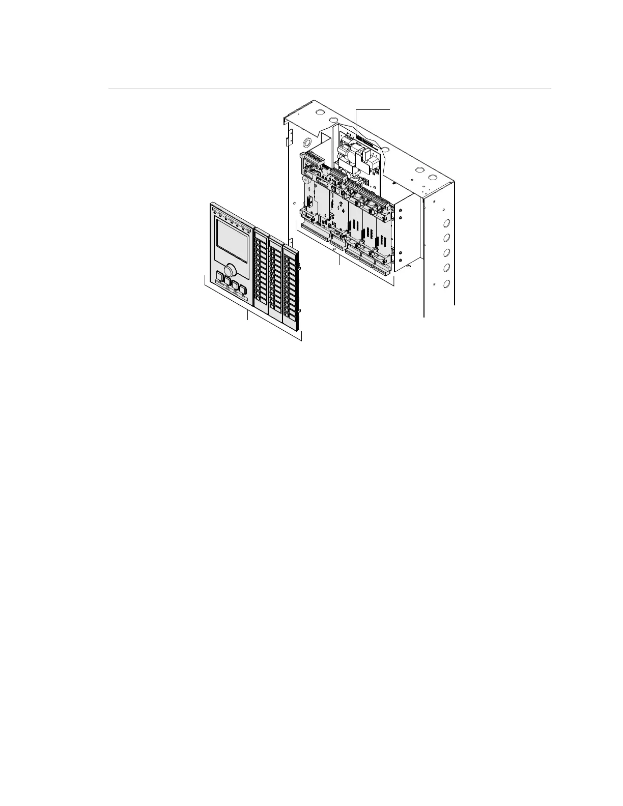
Figure 27: SFS1-ELEC chassis hardware and operator layer devices
(1) PS10-4B. A protective cage is installed over the power supply for ULC applications
(2) Hardware layer components (SFS1-CPU and option cards)
(3) Operator layer components (4X-LCD(-LC) and 4X Series control-display modules)
SFS1-CPU Main Board
The SFS1-CPU Main Board is a hardware layer board that processes all
information from modules installed in the same cabinet and from other control
panels on the life safety network. One main board is required for each panel in
an EST3X network. The SFS1-CPU is always installed on the first three card
slots.
One 3-SDC1 Signature loop controller module for signaling line circuit 1 (SLC1)
is preinstalled on the SFS1-CPU. The signaling line circuit supports up to
125 detector and 125 module addresses. It also provides dedicated non-
resettable 24 VDC for powering conventional two-wire smoke detector circuits on
Signature Series modules. Refer to the SFS1-CPU Main Board Installation Sheet
(P/N 3101773) for connecting field wiring and for specifications.
In an EST3 life safety system, a 3-SAC local rail module communicates on the
rail while talking to the 3-SFS1-CPU and various devices on the SPUR network.
In an EST3X life safety system, the SAC Manager exists as a firmware
subsystem on the SFS1-CPU and is treated like a virtual card. As such, it uses
the 3-SAC module’s firmware to emulate its functionality. The SAC Manager has
its own card address and set of device addresses.