Chapter 7: Service and troubleshooting
174 EST3X Technical Reference Manual
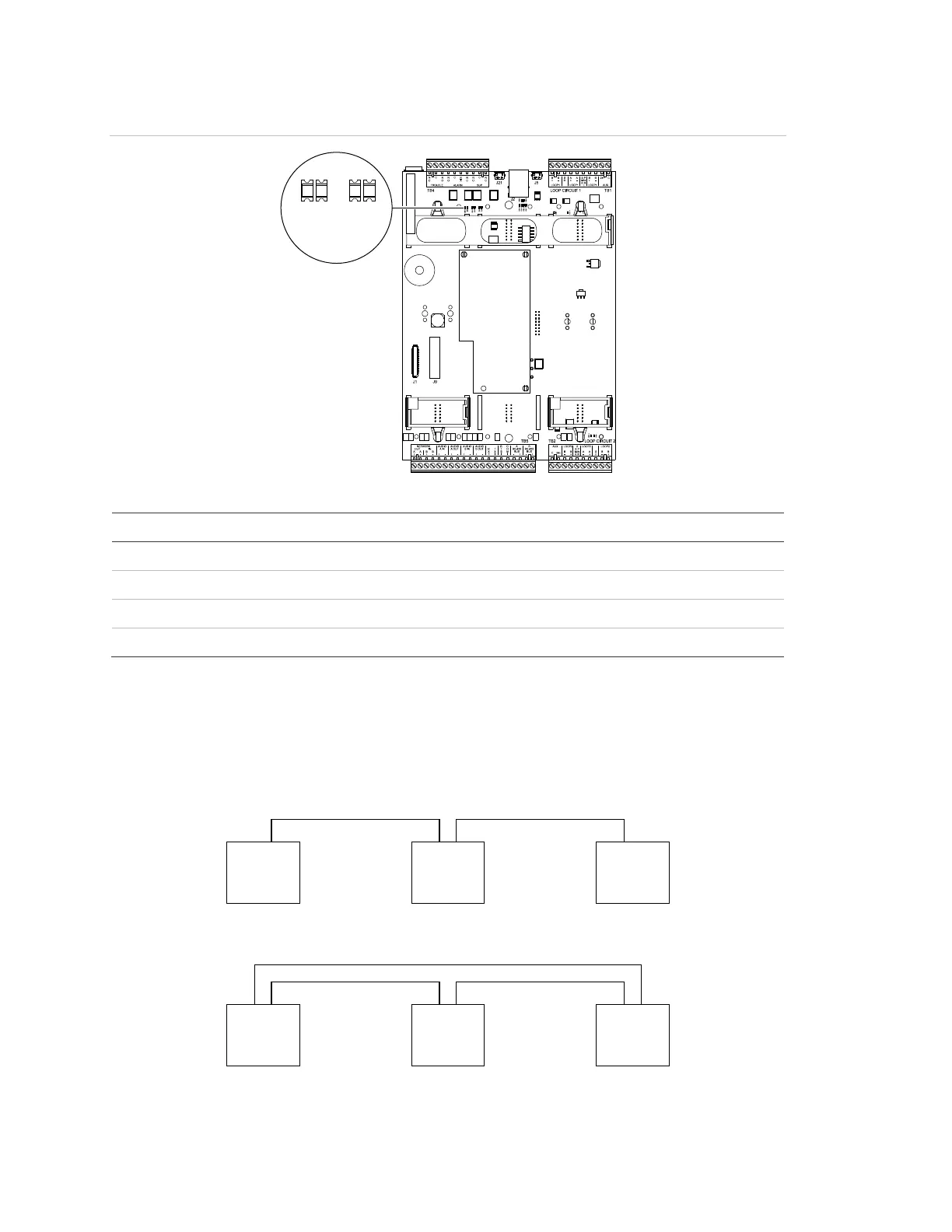
Figure 44: SFS1-CPU LEDs
Table 40: SFS1-CPU LED descriptions
Normal state Descriptions
Flashing Network data RX Class B activity
Flashing Network data TX Class B activity
Flashing Network data RX Class A activity
Flashing Network data TX Class A activity
Network data and digital audio risers
LEDs DS9, DS10, DS11, and DS12 in Figure 44 show the location and normal
state of the network communication status LEDs on the SFS1-CPU.
Network wiring alternates between channel A and channel B, as shown below.
A B
CPU
(1)
(2)
A B
CPU
A B
CPU
A B
CPU
A B
CPU
A B
CPU
(1) Class B network wiring one-line diagram
(2) Class A network wiring one-line diagram