Chapter 7: Service and troubleshooting
200 EST3X Technical Reference Manual
available. When the diagram is used in conjunction with the information provided
by the control panel, you can easily isolate open conditions or defective devices.
The loop shown in Figure 48 below will be used to illustrate basic troubleshooting
techniques.
Note: When troubleshooting Class A loops, disconnect the loop from the return
(loop A) terminals and temporarily jumper both loop A terminals to the respective
loop B terminals. You can then troubleshoot the loop as a Class B loop.
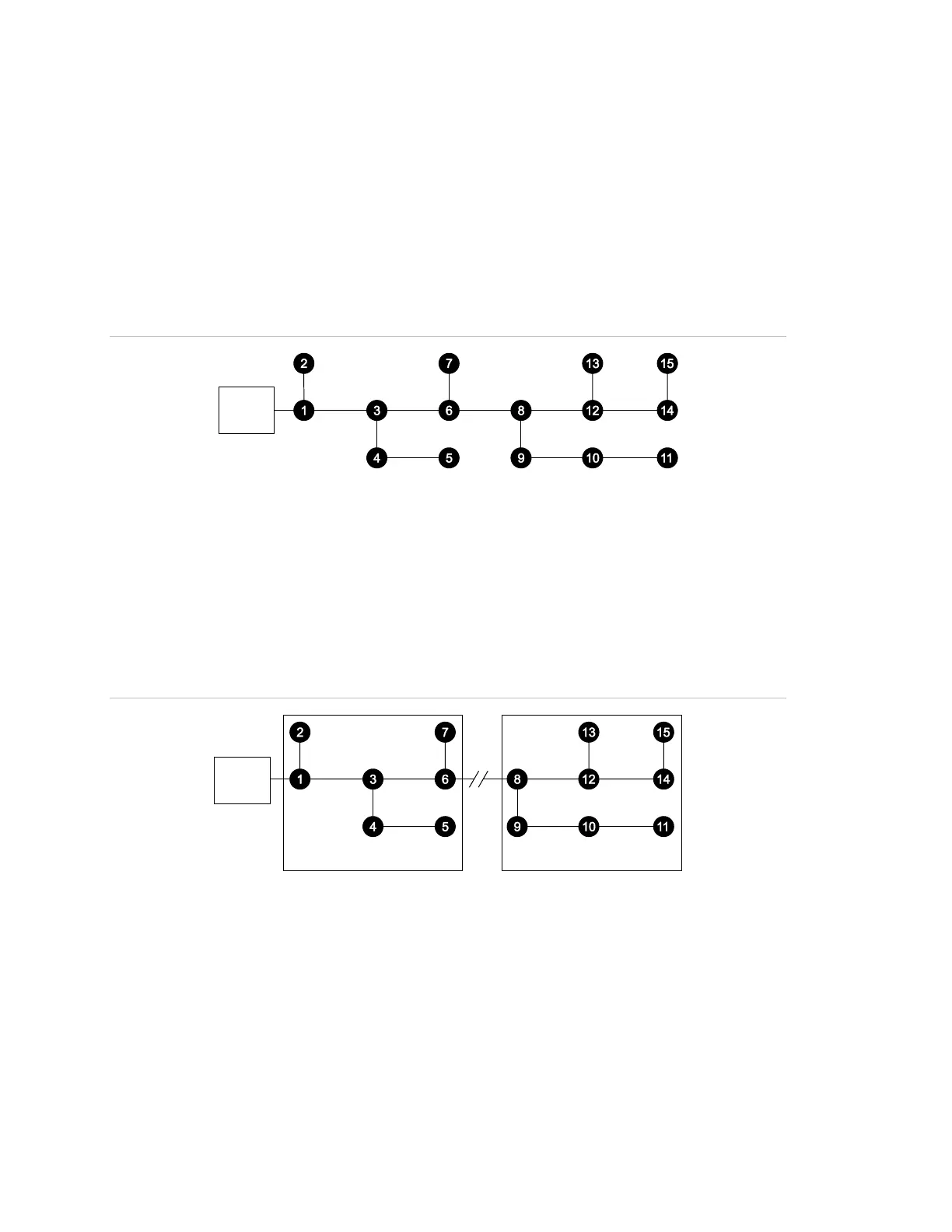
Figure 48: Normal Signature data loop topology
(1) Signature loop controller
Open circuit conditions
On a loop with an open fault, the Signature modules communicate with devices
up to the break and the control panel LCD screen displays a trouble condition for
all devices beyond the break. Figure 49 shows devices 1 through 7 continuing to
operate and devices 8 through 15 reporting device troubles.
Figure 49: Open fault on the data loop
(1) Signature loop controller
(2) Break in the loop
(3) Devices in trouble
(4) Devices operating normally
In Figure 49, a wire break or intermittent connection between devices 6 and 8 is
the most probable cause of the failure. Other possible causes include a device
failure in devices 9 through 15, failure to define them in the loop controller’s
database, or failure to define them correctly in the 3-SDU.