Chapter 7: Service and troubleshooting
EST3X Technical Reference Manual 203
Table 60: Ground fault indications
ser interface indications Ground fault location
GND Fault LED is on but no device trouble
e shows on the LCD screen
• Loop controller circuit
• 24 VDC smoke power circuit
GND Fault LED is on and a device trouble
message with the device addre
ss displays on
LCD screen
Positive leg of the input circuit for the device
Figure 52: Data loop ground faults
(1) Signature loop controller
(2) Ground fault location
(3) Positive ground fault
(4) Negative ground fault
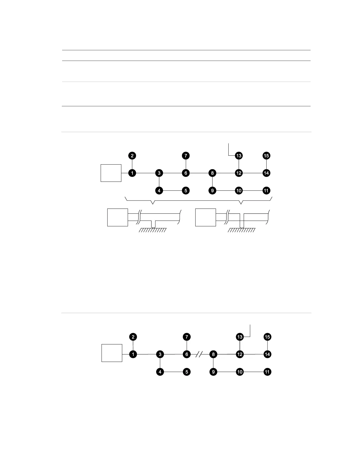
To isolate the ground fault, open the suspect loop (both conductors) at a point
that will disconnect approximately 50% of the installed devices as shown in
Figure 53. A similar technique is used on smoke power or module input circuits.
Figure 53: Data loop ground fault isolation
(1) Signature loop controller (ground fault LED Off)
(2) Both conductors open insolates the ground fault
(3) Ground fault