Chapter 7: Service and troubleshooting
EST3X Technical Reference Manual 207
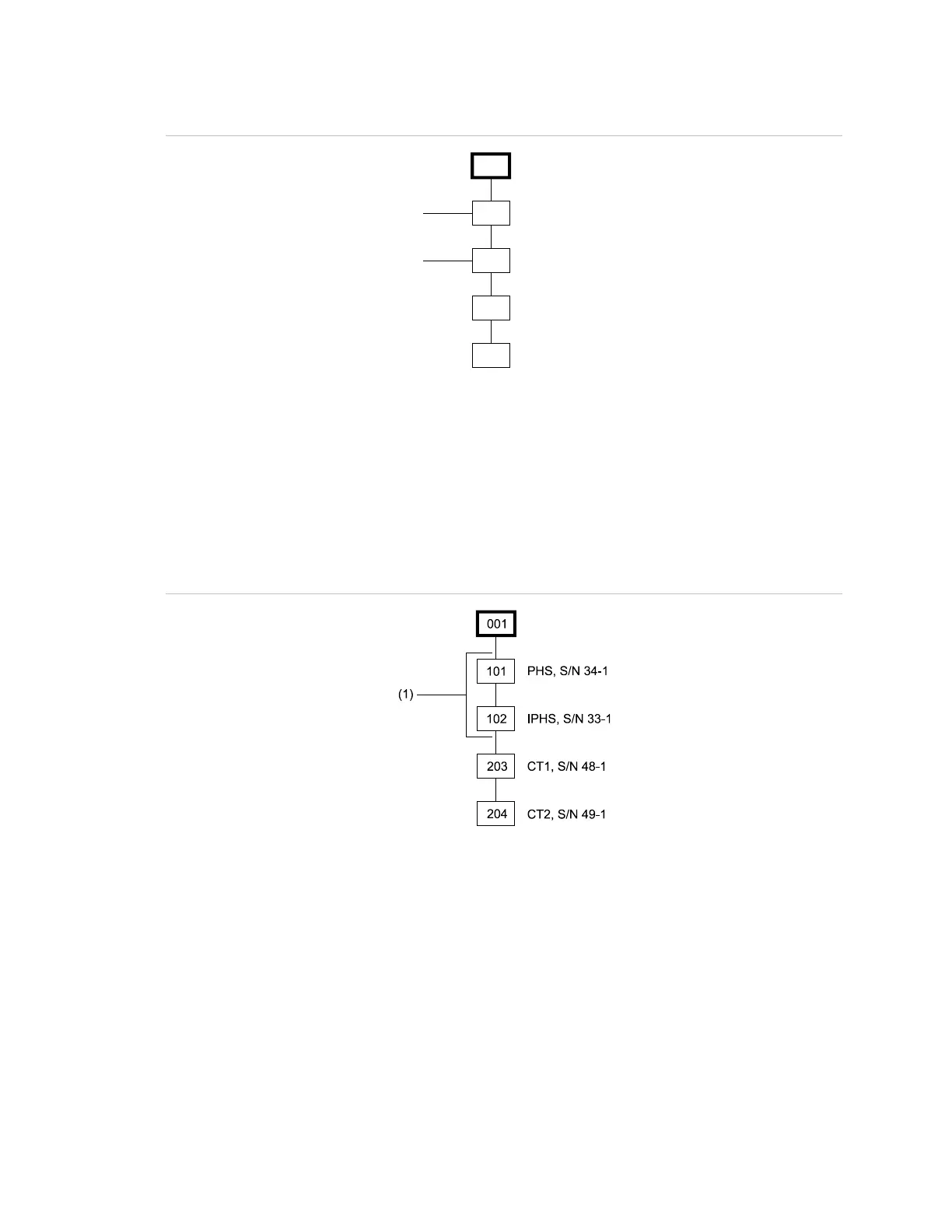
Figure 57: Both detectors returned to new locations
001
203
204
CT1, S/N 48-1
CT2, S/N 49-1
102
PHS, S/N 34-1
IPHS, S/N 33-1
101
(1)
(2)
(1) PHS, S/N 34-1 detector returned to service in new location before remapping
(2) IPHS, S/N 33-1 detector returned to service in new location before remapping
Figure 58 shows the map after remapping. Note that the new S/N-to-panel
address correlations have been made. The IPHS detector is now correlated with
address 102 and the PHS detector is correlated with address 101. The relocated
devices will now respond as programmed for the original address location.
Figure 58: Both detectors remapped
(1) Remapped detectors PHS, S/N 34-1 and IPHS, S/N 33-1
When a factory-new detector replaces an in-service detector, the new detector is
operational with a default address of 00 until it is mapped. When the loop is
remapped, the new detector is given the address assigned to its map location. If
a factory-new detector is added over and above the expected number of devices
on the loop, it is operational with a default address of 00. However, the panel
reports a trouble because the actual map contains one more device than the
expected map.