Appendix A: System calculations
254 EST3X Technical Reference Manual
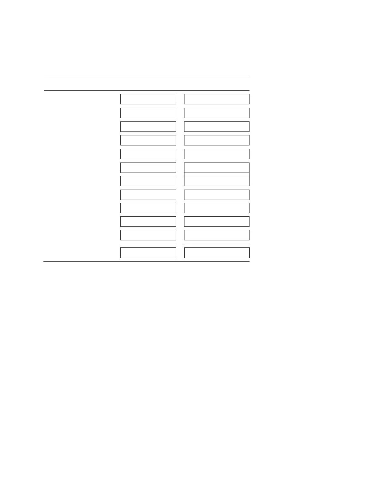
Worksheet C: AUX power current load
Instructions: For each NAC/AUX circuit used to provide AUX power, enter the total amount of standby and alarm
currents required by the devices powered by the circuit. Use the standby and alarm currents on the device installation
sheet for your calculations.
Standby
Alarm
NAC/AUX 1
NAC /AUX 2
NAC /AUX 3
NAC /AUX 4
SFS1-CPU Main Board
SIGA-REL module [1][2]
RPM module [1]
CDR-3 module [1]
IOP3A [1]
Total (mA)
[1] Do not include currents if the module is not installed.
[2] A maximum of ten SIGA-REL modules per signaling line circuit can be installed.