Chapter 3: Operating instructions
EST3X Technical Reference Manual 73
the control panel electronics chassis. A blank insert is provided for labeling the
LEDs and switches.
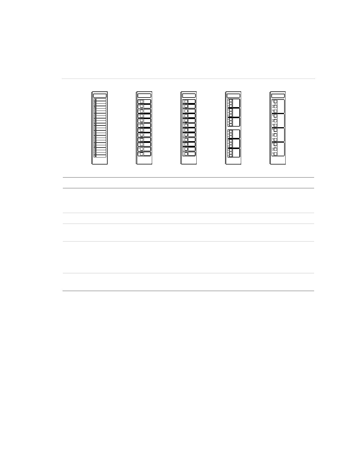
Figure 11: Control-display modules
Trouble
Trouble
Trouble
Trouble
Normal
Normal
Normal
Normal
(1)
(2) (3)
(4) (5)
Description
-24R
-24Y
-12RY
Twenty-four red LEDs
Twenty-four yellow LEDs
Twelve red-over-yellow LED pairs
-12SR Twelve LED-switches with red LEDs
-12/S1GY
-12/S1RY
Twelve LED-switches with green-over-yellow LEDs
Twelve LED-switches with red-over-yellow LEDs
-6/3S1G2Y
-6/3S1GYR
Six groups of three LED-switches with green LEDs (top switch), and
yellow LEDs (middle and bottom switch)
Six groups of three LED-switches with green LEDs (top switch), yellow
LEDs (middle switch), and red LEDs (bottom switch)
-4/3SGYWR Four groups of three LED-switches with green LEDs (top switch),
yellow-over-white LEDs (middle switch), and red LEDs (bottom switch)
The buttons on a control-display module use one of three available operating
modes that are database configured.
• Toggle: The state of the button changes each time the button is pushed (i.e.
“off” to “on” or “on” to “off”). Toggle buttons are commonly used to control
two-state operations such as on/off, open/close, speaker select, telephone
select, etc.
• Interlocked: Three adjacent toggle buttons that operate as a group. Pushing
any button in the group turns the output of the other two buttons “off” and
turns its own output “on.” The interlocked mode is commonly used for hands-
off auto control of HVAC systems. An interlocked button in the “on” state can
be turned “off” without activating a second button by pressing the “on” button