2-15
CrossPoint / MAV Matrix Switchers • Installation
Audio input and output (audio models)
By default, the audio ties follow the video ties. Audio breakaway, which
can be activated via the front panel or under Ethernet or serial port control,
allows you to select from any one of the audio input sources and route it
separatelyfromitscorrespondingvideosource.Seechapter3,“Operation”,
chapter4,“Programmer’sGuide”,chapter5,“MatrixSoftware”,andchapter6,
“HTMLOperation” for details.
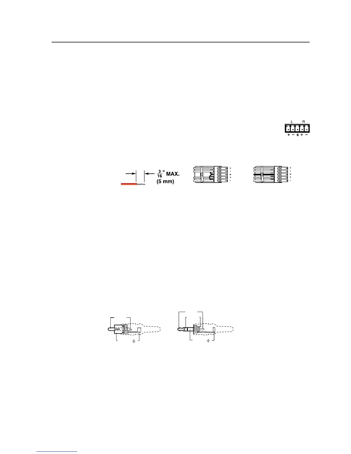
Captive screw connector models (all except MAV Plus 128 AV RCA)
d
Connections for balanced and unbalanced audio inputs —
Each input has a 3.5 mm, 5-pole captive screw connector for
balanced or unbalanced stereo audio input. Connectors are
included with each switcher, but you must supply the audio
cable.Seegure2-18towireaconnectorfortheappropriateinputtype.
Usethesuppliedtie-wraptostraptheaudiocabletotheextendedtailofthe
connector.Highimpedanceisgenerallyover800ohms.
L R
L R
Unbalanced Stereo Input
Balanced Stereo Input
(high impedance)
(high impedance)
Do not tin the wires!
Ring
Sleeve (s)
Tip
Sleeve
Tip
Sleeve
Tip
Tip
Ring
Figure 2-18 — Captive screw connector wiring for audio inputs
C
The length of the exposed (stripped) portion of the copper wires is
important. The ideal length is 3/16” (5 mm). Longer bare wires can
short together. Shorter bare wires are not as secure in the direct insertion
connectors and could be pulled out.
C
The captive screw audio connector can easily be inadvertently plugged
partially into one receptacle and partially into an adjacent receptacle. This
misconnection could damage the audio output circuits. Ensure that the
connector is plugged fully and only into the desired input or output.
N
See figure 2-19 to identify the tip, ring, and sleeve when you are making
connections for the switcher from existing audio cables. A mono audio connector
consists of the tip and sleeve. A stereo audio connector consists of the tip, ring
and sleeve. The ring, tip, and sleeve wires are also shown on the captive screw
audio connector diagrams, figure 2-18 and figure 2-20.
Tip (+)
Sleeve ( )
Sleeve ( )
Ring (
-
)
Tip (+)
RCA Connector
3.5 mm Stereo Plug Connector
(balanced)
Figure 2-19 — Typical audio connectors
The audio level for each input can be individually set via the front panel
or Ethernet or serial port control to ensure that the level on the output
doesnotvaryfrominputtoinput.Seechapter3,“Operation”,chapter4,
“Programmer’sGuide”,chapter5,“MatrixSoftware”,andchapter6,
“HTMLOperation” for details.