2. Assembly
2−35
Festo P.BE−CPX−SYS−EN en 0902e
Variant Mounting points
1 2
2
34
CPX terminal in plastic version with VTSA
pneumatics
Required mounting with:
Left end plate 1: two M4 or M6 screws
For each additional mounting bracket
(not shown, needed if 4 or more inter−
linking blocks are used, see Tab.2/4),
type CPX−BG−RW−...: one M4 screw
Pneumatic interface 2: two M6 screws
with internal hex
Optional: Mounting bracket 3 (second
variant not shown) for VTSA pneumatics
on the pneumatic supply plate: one M5
screw or one M5 and one M6 screw
Right end plate 4: two M6 screws
1
2
3
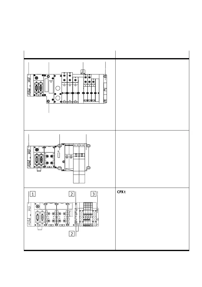
CPX terminal in plastic version with Midi/
Maxi pneumatics
Required mounting with:
Left end plate 1: two M4 or M6 screws
For each additional mounting bracket
(not shown, needed if 4 or more inter−
linking blocks are used, see Tab.2/4),
type CPX−BG−RW−...:one M4 screw
Pneumatic interface 2: two M6 screws
Right end plate 3: two M6 screws
1
2
2
3
CPX terminal in plastic version with CPA
pneumatics
Required mounting with:
Left end plate 1: two M4 or M6 screws
each
For each additional mounting bracket
(not shown, needed if 4 or more inter−
linking blocks are used, see Tab.2/4),
type CPX−BG−RW−...:
one M4 screw
Pneumatic interface:
two (optionally three) M4 screws 2
Right end plate 3: two M4 screws
Tab.2/6: Mounting points required for wall mounting (part 2)