150
DASHBOARD
AND CONTROLS
SAFETY
STARTING
AND DRIVING
WARNING LIGHTS
AND MESSAGES
IN AN EMERGENCY
MAINTENANCE
AND CARE
TECHNICAL
SPECIFICATIONS
INDEX
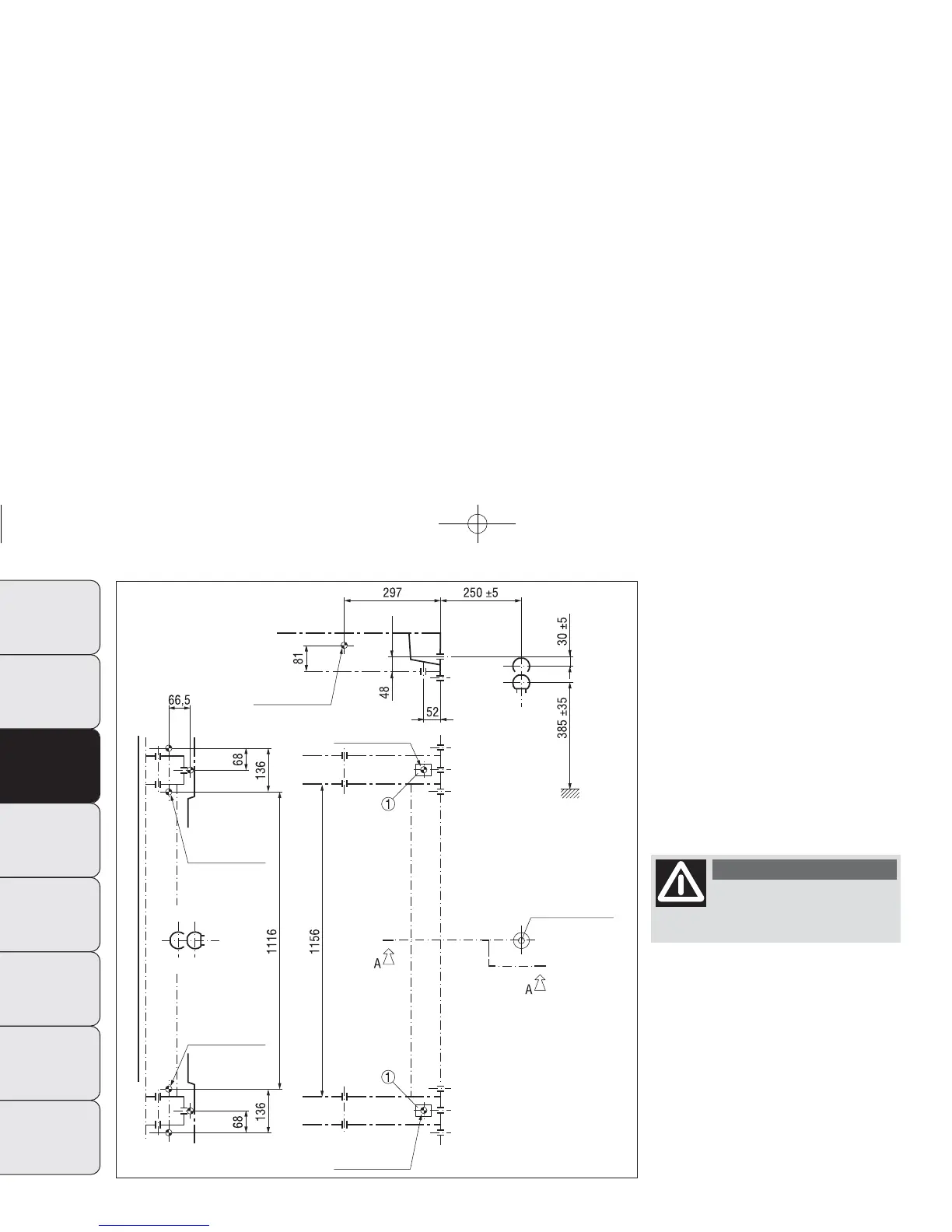
Installation diagram for Van
versions fig. 150
The tow hook structure must be fas-
tened in the points shown by the sym-
bol Ø using a total of 6 M10× 1.25
screws and 4 M12 screws.
The internal back plates are to be at
least 5 mm thick.
MAX LOAD ON BALL: 100/120 kg ac-
cording to the payload (see “Weights”
table in the “Technical data” section).
After fitting, the screw
holes must be sealed to
prevent exhaust gas leaks.
WARNING
fig. 150
F0N0189m
Existing hole
Existing nut
Existing nut
Existing hole
Existing hole
laden
Standard ball
M12
M12
M10 (3x)
M10 (3x)
M12
To install a tow hook, the bumpers
must be trimmed as described in the
supplier’s installation kit.
141-154 DUCATO LUM EN 12-02-2010 8:52 Pagina 150