F0N0251m
fig. 163
F0N0223m
fig. 162
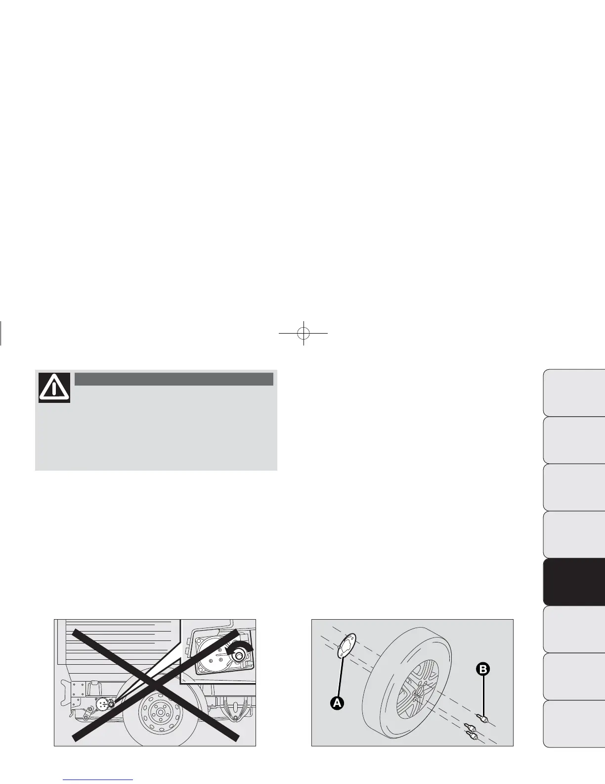
For vehicles with allow rims, proceed as follows:
– take the kit from the tool box;
– fit plate A-fig. 163 to the alloy wheel, securing with
screws B-fig. 163 provided with the wrench;
171
DASHBOARD
AND CONTROLS
SAFETY
STARTING
AND DRIVING
WARNING LIGHTS
AND MESSAGES
IN AN EMERGENCY
MAINTENANCE
AND CARE
TECHNICAL
SPECIFICATIONS
INDEX
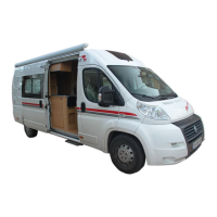
At the end of the operation of raising/
locking the spare wheel, the key must be
extracted, taking care not to turn it in the wrong
direction when trying to facilitate the extraction
of the actual key, to prevent the attachment de-
vice from being released and the wheel assembly
not being securely retained fig. 162.
WARNING
– refit the wheel to the mount and turn to the end of the
slot (as shown in fig. 164) and tighten the knob D-fig. 164;
– introduce the wheel removal wrench on the screw fig.
156 and turn it clockwise to allow the spare wheel to be
raised.
❒
Check that it is correctly positioned in the dedicated
housing under the floor pan (the lifting system has an
end of travel clutch which, if incorrectly positioned, will
be unsafe);
❒
place the removal spanner back in the tool box;
❒
place the tool box in its housing under the passenger seat.
165-198 DUCATO LUM EN 12-02-2010 8:43 Pagina 171