64
SECTION 3 - INDUSTRIAL APPLICATION
F32 SERIES
Base - April 2009 Print P2D32F005 E
Starting and
crankshaft
rotation
Balance
valves of
cylinder no.
Adjust
clearance of
intake and
exhaust valves of
cylinder no.
From 0.07 to 0.07 1 1
180 3 3
180 4 4
180 2 2
Revi - January 2010
On TIER 3 engines with internal EGR (F5CE9454, F5CE9484)
it is not possible to use the valve clearance adjustment
procedure in which all the valve clearances can be checked
using just 2 different crankshaft positions.
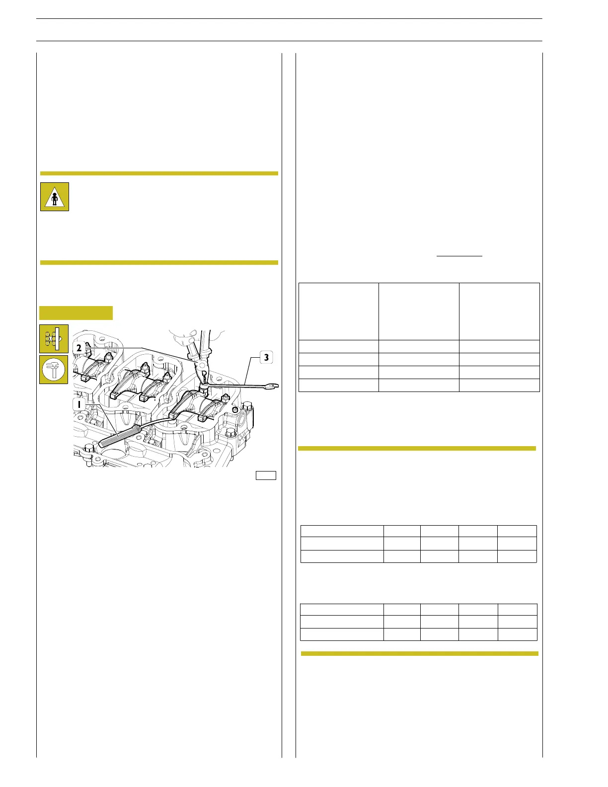
Check and setting of tappet clearance
Figure 108
128138
Each cylinder must be checked by taking it to the T.D.C. (top
dead centre) at the end of compression and adjusting the
clearance of both valves on the cylinder in question.
Position the crankshaft at TDC of cylinder 1(see figures 5 and
6).
Rotate crankshaft as required (see table) and check that intake
and exhaust valves are both closed and not in a balanced
position.
For cylinder 4 it is possible to check the correct position of the
crankshaft with tool 99360612.
Adjust the clearance between the rockers and valves using a
pair of pliers (2), a wrench (3) and a feeler gauge (1).
Clearance shall be as follows:
- intake valves 0.5 ± 0.1 mm
- exhaust valves 0.50 ± 0.1 mm.
FIRINGSEQUENCE1-3-4-
2
In order carry out a quicker adjustment of the
working slack between rocker arms and valves,
proceed as following:
Rotate the engine drive shaft, balance the valves of
cylinder 1 and adjust the valves identified by star
symbol, as indicated in the following table:
Rotate the engine drive shaft., balance the valves of
cylinder 4 and adjust the valves identified by star
symbol, as indicated in the following table:
Cylinder n
Suction
Exhaust
1
234
*
*
--
-
*
-*
Cylinder n
Suction
Exhaust
1
234
*
-
*-
-
-
*
*
For F5CE5454 engines
NOTE
Check of belt’s tear and wear status
Carefully verify the belt’s surface in order to detect any sign of
incision, crack, excessive wear in correspondence of toothing;
check end and surface grinding.
Danger: if the engine is switched off but is still hot,
unexpected motion of the belt may occur.
Wait for engine temperature cooling as a precaution
in order to avoid serious danger injury.