Figure 42
HEAD SCREW LOCKING ORDER
Screw s 1,2,3,4,5,6: M15x1,5 6g x193
Screws 7,8,9,10: M12 x1,5 6g x165
- Lubricate the screws;
- Tighten the screws with a torque wrench following the
locking order described above:
M15 Screws: torque 130±6,5Nm;
M12 Screws: torque 65±3,25Nm;
- Tighten the screws furth er with a torque wren ch
following the locking order described above:
M15 Sc rews: 90˚;
M12 Sc rews: 90˚;
- Wait a few minutes for settling;
- Then apply the final angular closing following the locking
order described above:
M15 Sc rews: 70˚;
M12 Sc rews: 60˚.
133184
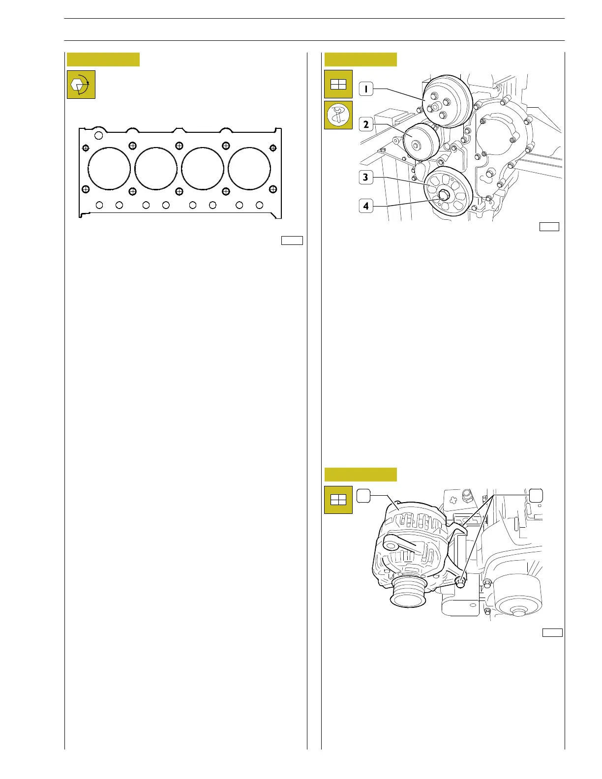
Figure 43
- Reassemble the electromagnetic joint support (1).
- Reassemble the pulley (2).
- Reassemble the pulley (3), tighten the fastening screw
(4) to the prescribed torque setting.
- Reassemble the heat exchanger reminding to replace the
old gasket with a new one; tighten the fastening screws
to the prescribed torque setting.
125128
Figure 44
75686
1
2
- Put the alternator back in place (1).
- Screw up without tightening (2).
α
1
234
7
426
10
8
3
1
5
9
SECTION 3 - INDUSTRIAL APPLICATION
19
F32 SERIES
Pri nt P2D32F005 E Base - April 2009
Revi - 12.2012