119111
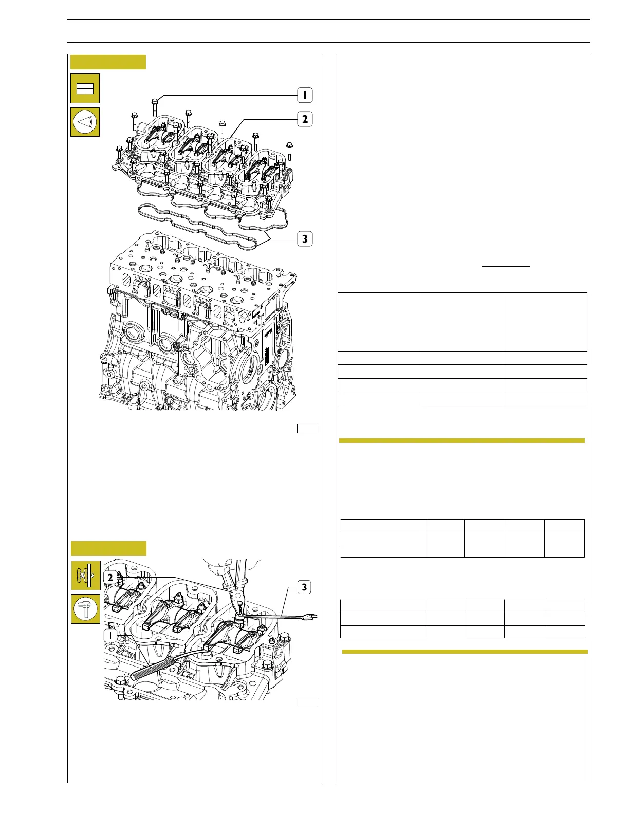
Figure 49
- Replace the gaskets (3), reassemble the rocker arm
holding case (2) and tighten the fastening screws to the
prescribed torque setting.
- After having completed the assembly, check that the
rocker arms are correctly positioned on the valves and
the tappet control rods.
Figure 50
128138
On TIER 3 engines with internal EGR (F5CE9454,
F5CE9484) it is not possible to use the valve clearance
adjustment procedure in which all the valve clearances can
be checked using just 2 different crankshaft positions.
Each cylinder must be checked by taking it to the T.D.C. (top
dead centre) at the end of compression and adjusting the
clearance of both valves on the cylinder in question.
Position the crankshaft at TDC of cylinder 1.
Rotate cranksh aft as required (see table) and check that
intake and exhaust valves are both c losed an d not in a
balanced position.
For cylinder 4 it is possible to check the correct position of
the crankshaft w ith tool 99360612.
Adjust the clearan ce between the rockers and valves using
a pair of pliers (2), a wrenc h (3) and a feeler gauge (1).
Clearance shall be as follows:
- intake valves 0.5 ± 0.1 mm
- exhaust valves 0.50 ± 0.1 mm.
FIRINGSEQUENCE1-3-4-
2
For F5CE5454 engines
In order carry out a quicker adjustment of the
working slack between rocker arms and valves,
proceed as following:
Rotate t he engine drive shaft, balance the valves of
cylinder 1 and adjust the valves identified by st ar
symbol, as indicated in the following table:
Rotate the engine drive shaft., balance the valves of
cylinder 4 and adjust the valves identified by st ar
symbol, as indicated in the following table:
NOTE
Cylinder n
Suction
Exhaust
1
234
*
*
--
-
*
-*
Cylinder n
Suction
Exhaust
1
234
*
-*-
-
-
*
*
SECTION 3 - INDUSTRIAL APPLICATION
21
F32 SERIES
Pri nt P2D32F005 E Base - April 2009
Starting and
crankshaft
rotation
Balance
valves of
cylinder no.
Adjust
clearance of
intake and
exhaust valves of
cylinder no.
1toTDC 1 1
180 3 3
180 4 4
180 2 2
Revi - January 2010
 Loading...
