Each peripheral is defined as a structure in this case it is ADC_tag, and then memory is mapped
following the offset mentioned in the reference manual. MCR’s offset is zero so it is directly
located at the beginning of the ADC_tag structure. It is defined as a union of a 32-bit register and
a total 32-bit bit-field made of different fields of the register. Therefore while writing the whole
register you need to use ADC.MCR.R but for accessing a specific field you’ll need to use
ADC.MCR.B.CTUEN for instance. The compiler will take care of masking and shifting to only alter
the field in question to only modify it (but if the optimisation level is too high, unpredicted
behaviour might occur with these fields).
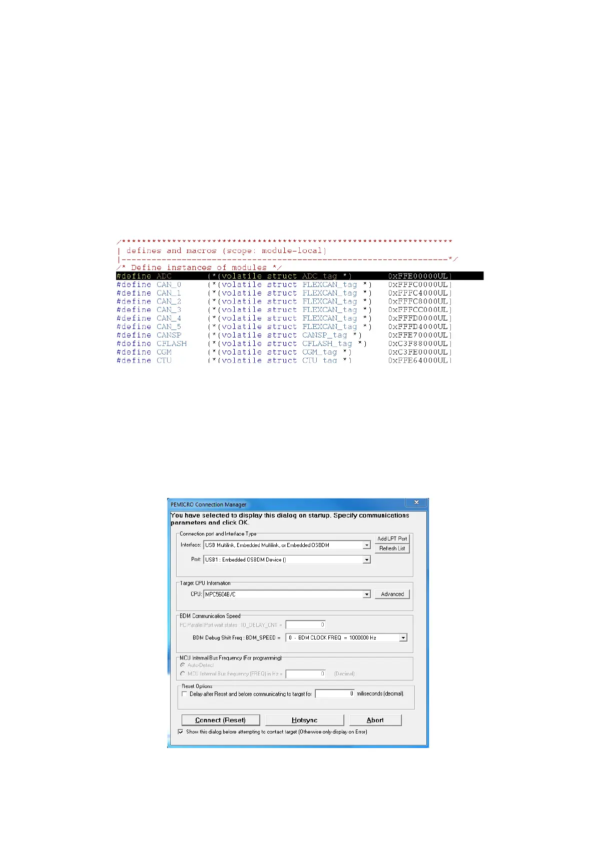
At the end of the mapping file, a volatile variable based on each peripheral structure is mapped
to the memory and ready to be used by the main program:
Now we will show how debugging works. About the microcontroller programming on the
starting kit: if you want to download to the flash using USB, the board must be powered up from
the USB and you can program it directly using the embedded programmer. If you have to use the
external source’s voltage regulator (or SBC) you’ll have to program it using a Multilink JTAG
interface (make sure you connect it on the right direction).
For debugging, click on debug, when you ensure that your device is connected and its driver is
installed.