Q.series
Gantner Instruments GmbH
29
4 Connecting the modules → Connecting the power supply
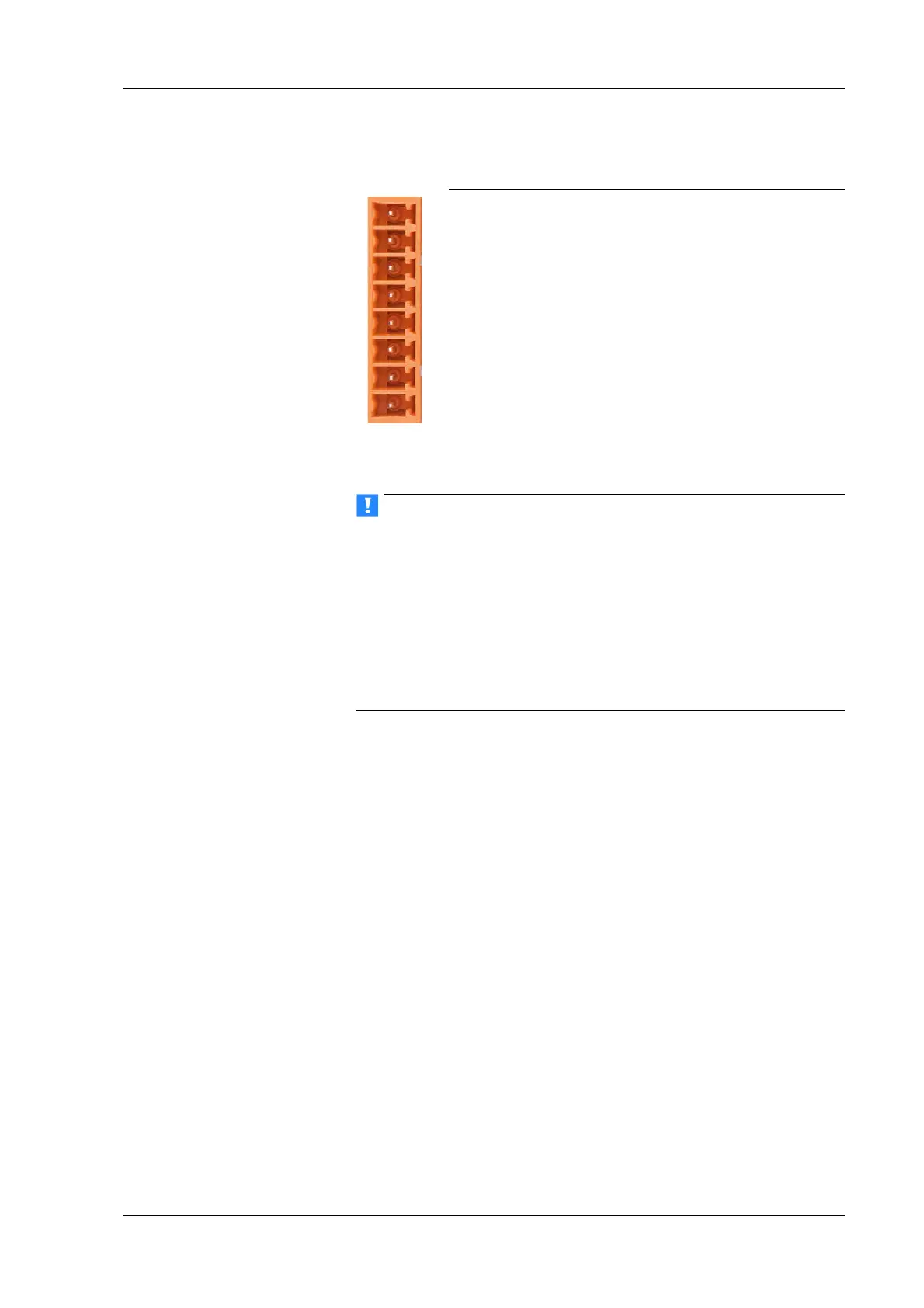
Fig. 4-6 Assignment for the base socket contacts (plan view).
When the modules are switched on, there is an increase current
demand until the modules are operating in a stable manner: In
the start-up phase up to 700
mA (10 ms) per module is needed
depending on the supply voltage. Thereafter, you should expect
approx. 500 mA per module for a 10 V supply voltage, with a 30 V
supply voltage
approx. 170 mA. You should therefore either use
power suppl
ies which can deliver the required peak power when
the voltage is switched on or – with many modules – switch the
modules on in several groups.
The modules have an internal self-healing (reversible) fuse for
protection against overvoltages, overcurrents and incorrect
polarity.
➡ Do not use cable which is too thin for the connection so that the
required power can be transferred to the module without signifi-
cant losses.
The cable diameter, which can be conne
cted to the terminals, is
0.14 mm
2
minimum and 1.5 mm
2
maximum or with wire-end
sleeves without plastic sleeves 0.25 mm
2
and 1.5 mm
2
and with
plastic sleeves between 0.25 mm
2
and 0.5 mm
2
. In total no more
than 16 modules should be supplied through their bases con-
nected together. With more modules another supply line is neces-
sary, for example via the Q.bloxx Extension Socket QES.
➡ The extension socket only supplies the module situated to the
right of it and the modules located to the left of it require a power
supply via the socket located on the far left.
Pin assignment
Sync A
UART 2B
UART 2A
Sync B
Supply +10 to 30 V
DC
Supply 0 V
UART 1B
UART 1A

 Loading...