Q.series
Gantner Instruments GmbH
31
4 Connecting the modules → Connecting interfaces
4.4 Connecting interfaces
You have several options for communicating (configuration and
data interchange) with the modules. You can:
• Connect the modules first to a Q.gate or Q.pac (Section 4.4.1
and Section 4.4.2, from page 31 onwards) and then connect
to a PC or PLC via Ethernet (Section 4.4.3, page 34) or one of
the optional field buses (EtherCAT, PROFIBUS-DP or
CANopen)
. The configuration is carried out exclusively via the
Ethernet interface.
For setting an IP address or for logging purposes you can also
use the
RS-232 interface of the Q.gate or Q.pac Test Con-
troller (Section 4.4.4, page 35).
• Connect single modules directly to the PC or a PLC; refer to
Section 4.4.5 from page 36 onwards.
For the serial interface cables use tw
o-wire, twisted cables, with
a screen if possible. Section 6.1, Using serial interfaces,
page 135
provides comprehensive instructions for setting up
serial interface links.
For Ethernet and EtherCAT we recommend
the use of cables to
Cat-5e or better.
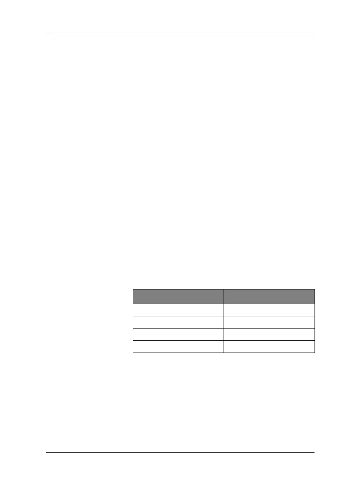
The module baud rate set as shipped is 24 MBaud (factory set-
ting). Depending on the length of the interface cable, you may
have
to re
duce the speed of data transmission; refer to the follow-
ing table. The overall length of the interface cable consists of the
le
ngth of all cables between the individual modules and the cable
length to the Test Controller or PC.
4.4.1 Connecting modules to Q.gate
The Q.gate Test Controller can be inserted into a base just like a
normal Q.bloxx module. However, only use the far left or far right
base, because the module has integral terminating resistances
and therefore terminates this end of the interface line. Any set
base address is ignored by the Test Controller.
Cable length in meters Maximum baud rate
1000 < 500 kBaud
100 < 1500 kBaud
20 < 6000 kBaud
10 >6 to 48 MBaud

 Loading...