Q.series
Gantner Instruments GmbH
137
6 Functional Procedures → Using serial interfaces
screen of the transducer line to the terminal with the earth sym-
bol.
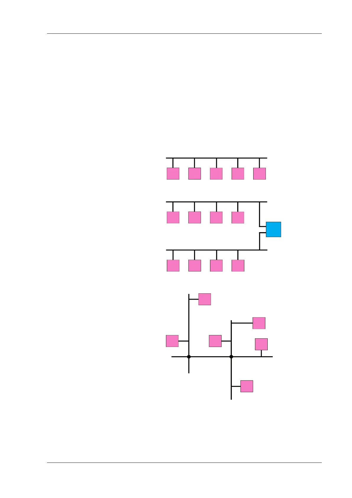
6.1.4 Network topologies
For setting up networks various network structures, or so-called
topologies, are possible. When connecting the Q.bloxx modules
and Test Controller, a simple line or bus structure is required
(Fig. 6-1); several “lines” can be brought together by the Test
Controller and the UARTs present in the Test Controller (Fig. 6-
2). Other topologies, for example the tree structure (Fig. 6-3)
used with Ethernet, are not admissible
Fig. 6-1 Line or bus structure.
Fig. 6-2 Combination of two lines on the Test Controller.
Fig. 6-3 Tree structure.

 Loading...