Vers. No. 6.1
66 Released: 25/04/2017
4 Connecting the modules → Q.bloxx A107: Connecting sensors
Voltages which exceed the admissible limits produce incorrect
measurement data, because the inputs are protected against
overvoltages and limit the input voltage.
Fig. 4-53 A107, measurement of voltage.
4.14.2 Current
A shunt resistance of 50 is integrated into the Q.bloxx Module
A107 for current measurement. This facilitates the measurement
of currents of up to 25 mA. For higher currents use a voltage mea-
surement and an external shunt; refer to Section 6.5, page 147.
Fig. 4-54 A107, measurement of current.
4.14.3 Potentiometer
Potentiometers with resistances between 1 k and 10 k are con-
nected in a three-wire configuration.
Fig. 4-55 A107, measurement with potentiometers.
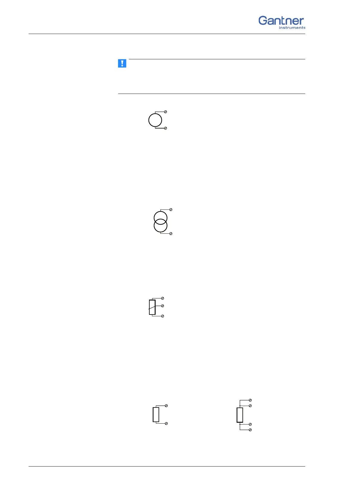
4.14.4 Resistance, Pt100, Pt1000
You can connect resistances and Pt100/1000 probes in two-wire
or four-wire circuits. You specify the selected type of circuit
during the module configuration (Type column).
Fig. 4-56 A107, measurement of resistance and Pt100/1000 probes.
2-wire circuit 4-wire circuit
1, 6
2, 7
1, 6
4, 9
2, 7
3, 8

 Loading...