Q.series
Gantner Instruments GmbH
49
4 Connecting the modules → Q.bloxx A101: Connecting sensors and I/O
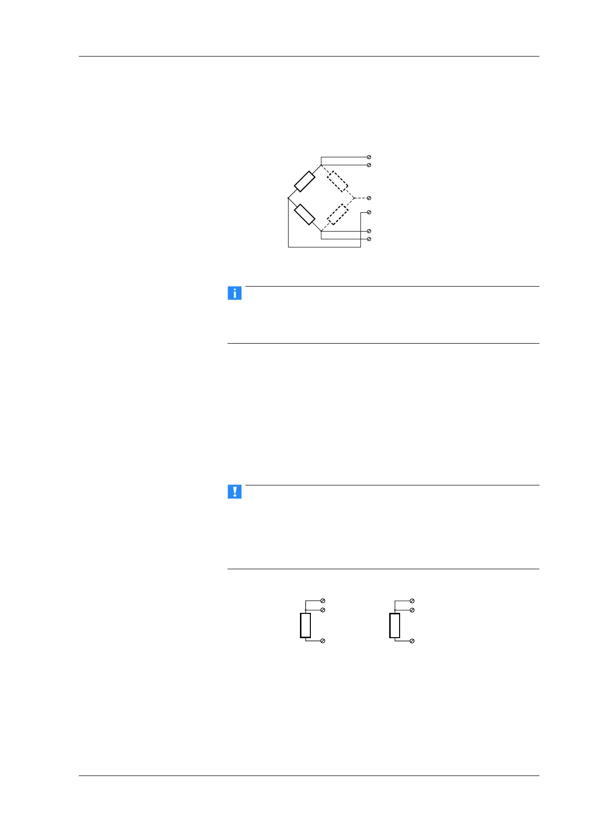
bridges the side drawn in dashes and the connection 5 are omit-
ted.
The bridge excitation voltage is 2.5 V.
Fig. 4-24 A101, measurement with full and half bridges.
Information about the types of circuit and the respective advan-
tages and disadvantages can be found in Section 6.3, Connecting
sensors with sensing leads, page 143.
4.8.7 Strain-gauge quarter bridges
For the connection of strain-gauge quarter bridges you need a
special connecting plug which contains the completion resis-
tances. The plug can be obtained under the designation Q.bloxx
Termi
nal B4/120-A101 with120 or B4/350-A101 with 350 from
Gantner Instruments GmbH.
The brid
ge excitation voltage is 2.5 V.
The plug must have the same resistance values as the strain
gauges used, because otherwise no measurement is possible.
Since, for reasons of stability, all necessary completion resis-
tances are located in the Q.bloxx Terminal, you have to select a
full bridge circuit as the bridge type for the channel.
Fig. 4-25 A101, measurement with strain-gauge quarter bridge
using Q.bloxx Terminal B4.
4.8.8 IEPE/ICP
®
sensor
The sensor is supplied with 4 mA of current from the module (cur-
rent supply).

 Loading...