Vers. No. 6.1
44 Released: 25/04/2017
4 Connecting the modules → The modules and their connection options
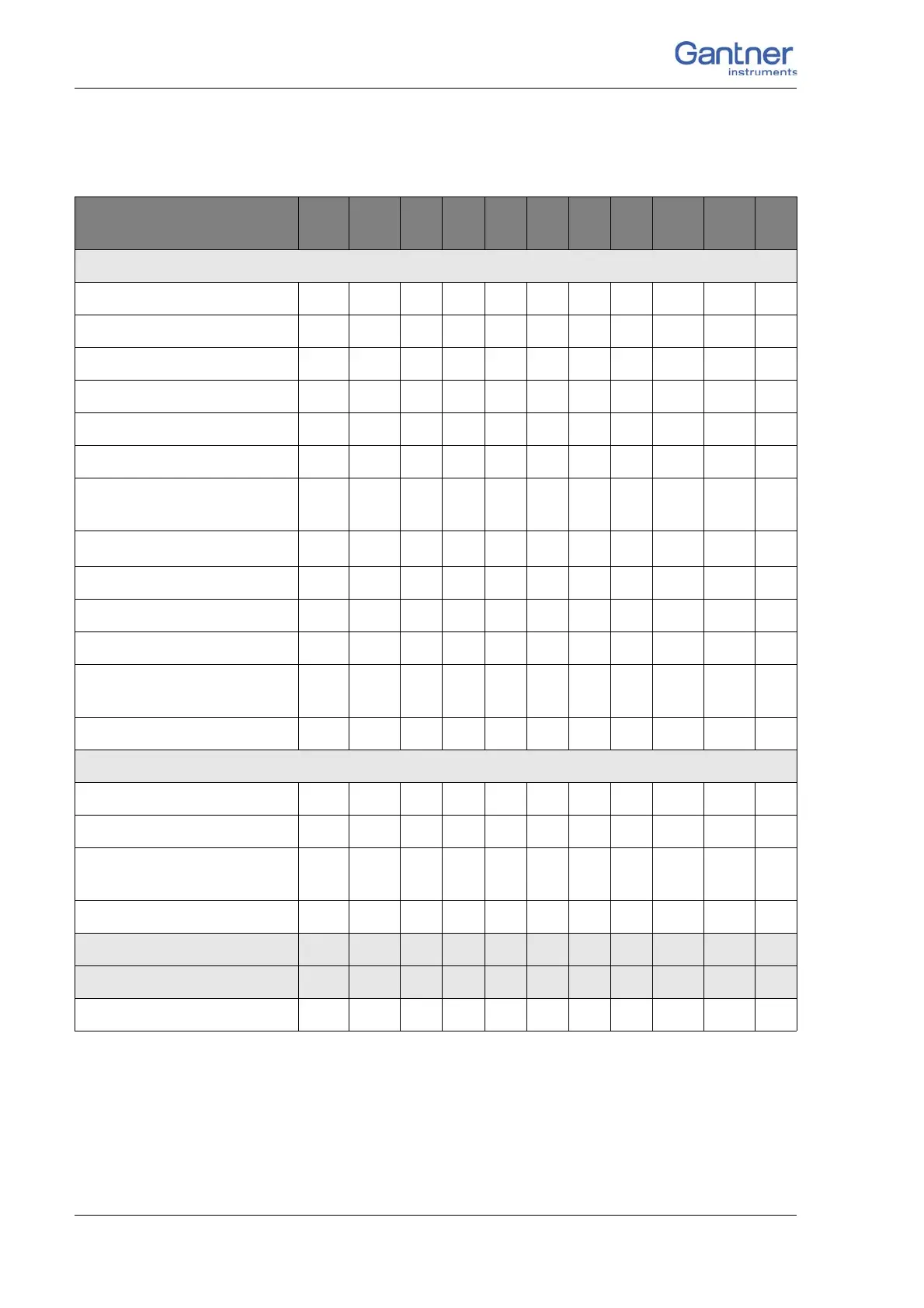
4.7 The modules and their connection options
1)
Half bridge only with Q.bloxx Terminal
2)
Quarter bridge with Q.bloxx Terminal
Modules:
A
101
A
102
A
103
A
104
A
105
A
106
A
107
A
108
A
109
A
111
A
116
Signal inputs
Voltage X X X X X X X
Current X X X X X
Potentiometer X X
Resistance X X X
Pt100, Pt1000 X X X
Thermocouple X X X
(Strain gauges) full + half
bridge
XX X
X
1)
X
Strain-gauge quarter bridge
X
2)
X
2)
X
2)
X
2)
X
Inductive full and half bridge X
LVDT, RVDT X
IEPE/ICP
®
Sensor X X X
Digital input: frequency,
pulse width, counter
X
Digital input: Status X X X X X X
Signal outputs
Voltage X X X
Current X X
Digital output:
frequency, pulse width
X
Digital output: Status X X X X X X
Number of channels 2 1 8 8 4 2 4 8 4 4 8
Data rate (in Hz)
100 k 100 k 100 100 10 10 k 10 k 10 k 100 k 100 k 10 k
For description refer to page 46 51 55 57 59 61 65 69 71 73 75

 Loading...