Q.series
Gantner Instruments GmbH
45
4 Connecting the modules → The modules and their connection options
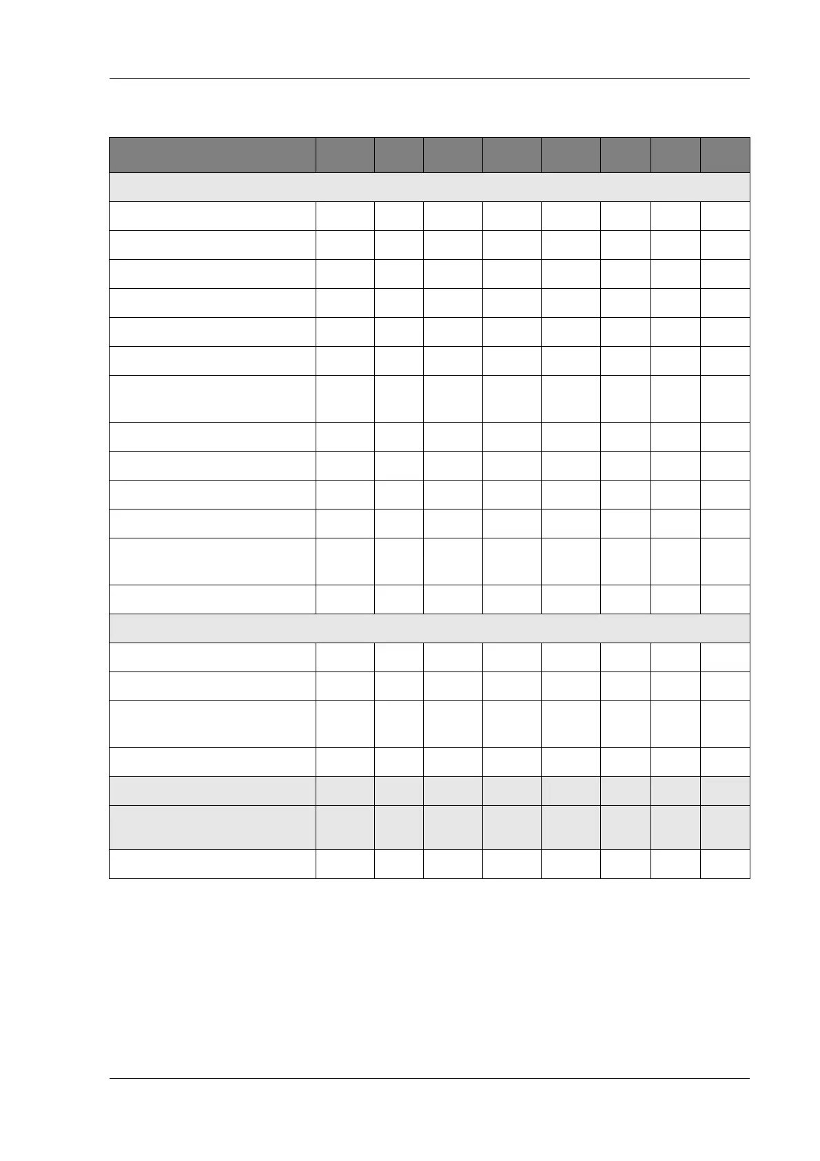
Modules:
A 123 A 124 A 127 A 128 D 101 D 104 D 105 D 107
Signal inputs
Voltage XXX X
Current
Potentiometer
Resistance
Pt100, Pt1000
Thermocouple X
(Strain gauges) full + half
bridge
Strain-gauge quarter bridge
Inductive full and half bridge
LVDT, RVDT
IEPE/ICP
®
Sensor
Digital input: frequency, pulse
width, counter
XX
Digital input: Status X X X
Signal outputs
Voltage
Current
Digital output:
frequency, pulse width
X
Digital output: Status X X
Number of channels 4 4 4 4 8 16 16 6
Data rate (in Hz)
100 k 10 k 100 k 100 k
up to
100 k
10 k 10 k 1 M
For description refer to page 83 85 87 89 91 94 96 97

 Loading...