Q.series
Gantner Instruments GmbH
61
4 Connecting the modules → Q.bloxx A106: Connecting sensors and I/O
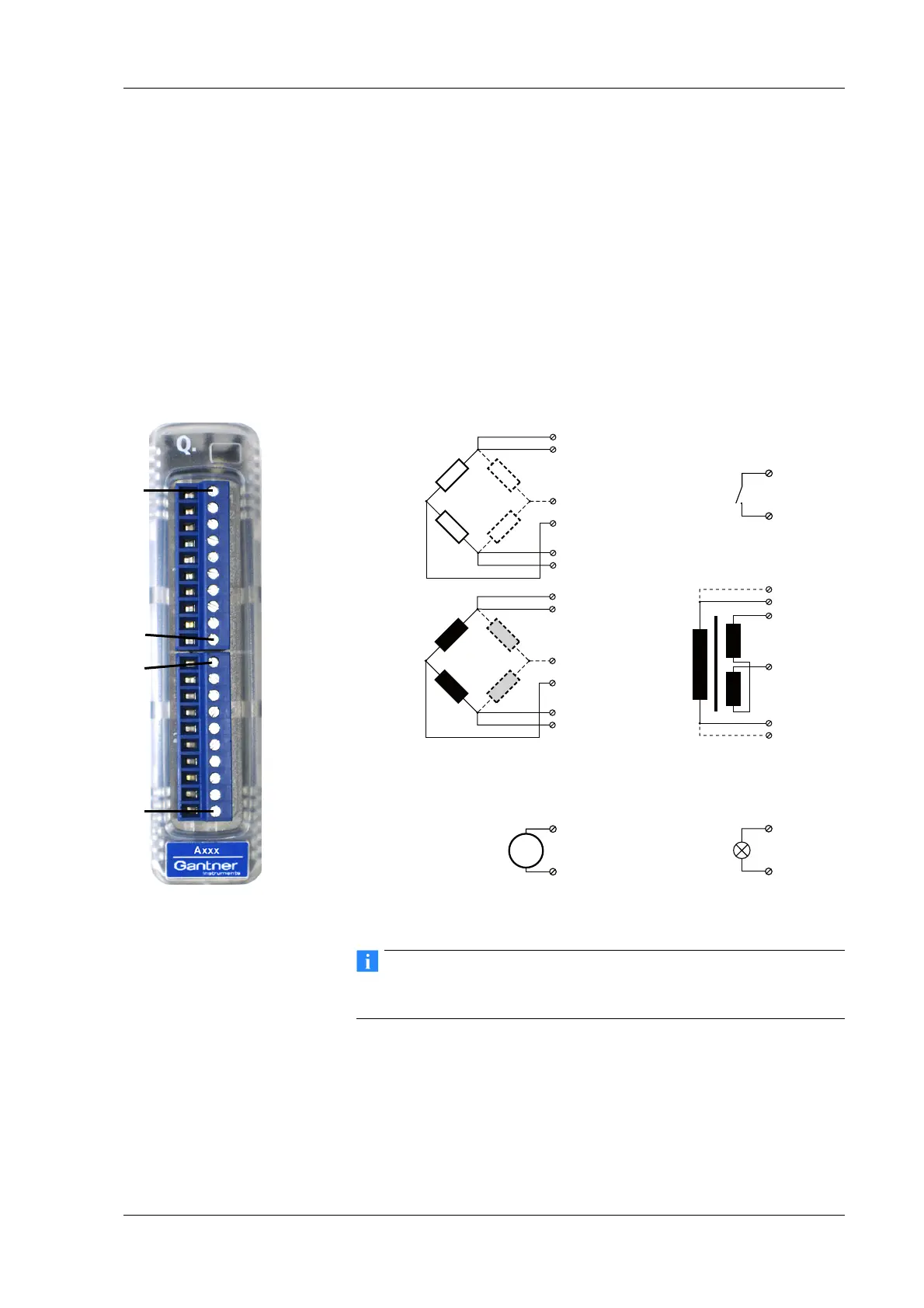
4.13 Q.bloxx A106: Connecting sensors and I/O
The Q.bloxx Module A106 has two electrically isolated analog
inputs, two analog outputs and four digital inputs and outputs.
The pin assignment of the two connector strips is identical and
the connection terminals have numbers for identifying the con-
nections.
GND identifies the analog and the measurement ground, 0 V and
+V
refer to the (external) supply voltage connections. Measure-
ment ground/GND and (module) supply volt
age are electrically
isolated in the module. The measurement ground for input and
the analog ground (output) are identical.
Fig. 4-45 Pin assignment for Q.bloxx Module A106.
Further information on transducers and sensors can also be
found in Chapter 6 ff. page 135.
4.13.1 Full and half-bridge transducers
With (resistive) full bridges (strain-gauge full bridges) all connec-
tions are occupied. If the sensor has no
sensing leads, you specify
this during the module configuration (Type column). With half
U
D
in
1, 2
+V
0V
1, 2
9
(10)
5 (+)
6 (–)
10
9
5 (+)
6 (–)
7
8
7
8
1DO 1
2DO 2
3A
Out
+
4GND
5U
Exc+
6U
Exc–
7U
Sen+
8U
Sen-
9U
Sig+
10 U
Sig-
1DO 1
2DO 2
3A
Out
+
4GND
5U
Exc+
6U
Exc–
7U
Sen+
8U
Sen-
9U
Sig+
10 U
Sig-
10110 1Plug 1Plug 2

 Loading...