Q.series
Gantner Instruments GmbH
59
4 Connecting the modules → Q.bloxx A105: Connecting sensors
4.12 Q.bloxx A105: Connecting sensors
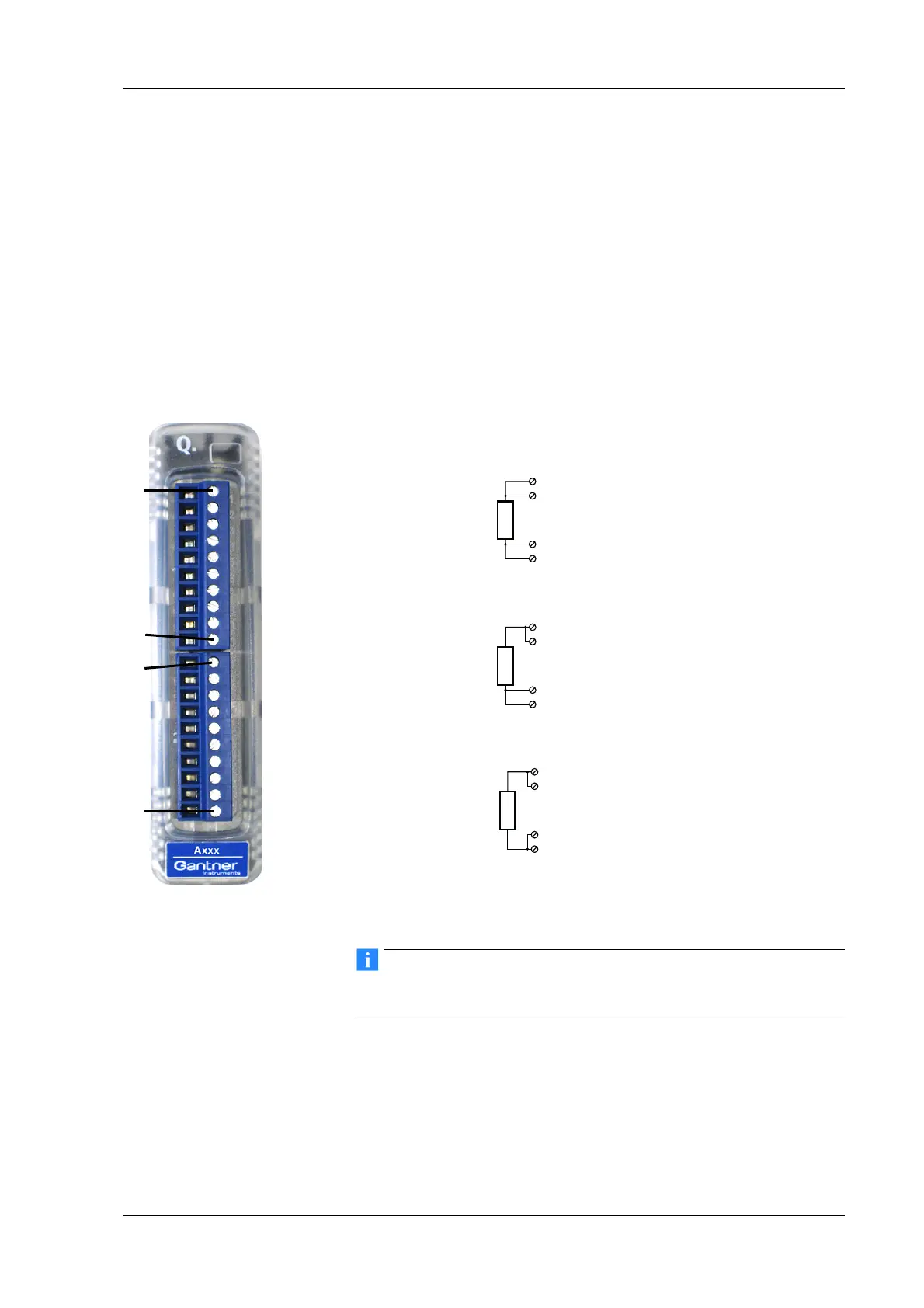
The Q.bloxx Module A 105 has four electrically isolated analog
inputs. The pin assignment of the two connector strips is identical
and the connection terminals have numbers for identifying the
connections. You will find the associated figures in each case at
the same place in the circuit diagrams, for example each of the
figures quoted in the second place belong to one possible connec-
tion method.
GND identifies the measurement ground of an input; measure-
ment ground and the (module) supply voltage are electrically iso-
lated in the module.
Fig. 4-43 Pin assignment for Q.bloxx Module A105.
Further information on transducers and sensors can also be
found in Chapter 6 ff. page 135.
4.12.1 Resistance, Pt100, Pt1000
You can connect resistances and Pt100/1000 probes in two-wire,
three-wire or four-wire circuits. However, you must in each case
connect all the terminals, i.e. you specify the circuit used for the
type of circuit when configuring the module (Type column), but
10110 1Plug 1Plug 2
2, 7
5, 10 (GND)
4, 9
3, 8
1–
2A
In
1
3A
In
2
4A
In
3
5GND
6–
7A
In
4
8A
In
5
9A
In
6
10 GND
1–
2A
In
1
3A
In
2
4A
In
3
5GND
6–
7A
In
4
8A
In
5
9A
In
6
10 GND
2-wire circuit
3-wire circuit
2, 7
5, 10 (GND)
4, 9
3, 8
2, 7
5, 10 (GND)
4, 9
3, 8
4-wire circuit

 Loading...