Vers. No. 6.1
78 Released: 25/04/2017
4 Connecting the modules → Q.bloxx A116: Connecting sensors
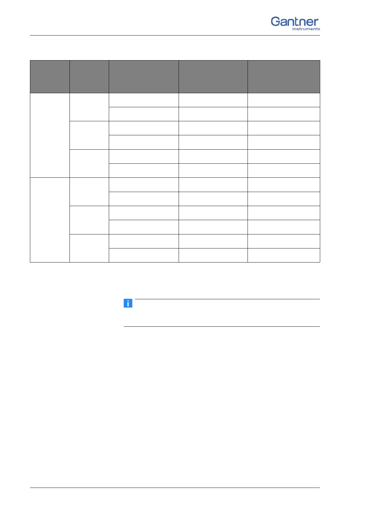
Fig. 4-72 Assignment of the cores for a cable termination with free
ends Cable A116.
Further information on transducers and sensors can also be
found in Chapter 6 ff. page 135.
4.18.1 Full and half-bridge transducers
With (resistive) full bridges (strain-gauge full bridges) six connec-
tions are used per measuring point. If the sensor has
no sensing
leads, you specify this during the module configuration (Type col-
umn); the U
Sen
inputs then remain open. With half bridges the
side drawn in dashes and the U
Sig-
connection are omitted.
The bridge excitation voltage is 2 V
DC
; with 350 sensor resis-
tance you can also use 4 V
DC
. The internal shunt resistance can
be activated also with full and half bridges.
7
Pair 1
Green
U
Exc+
A27
Green/black
U
Exc–
A28
Pair 2
Light blue/green
U
Sen+
B28
Light blue/yellow
U
Sen–
A29
Pair 3
Light yellow
U
Sig+
B27
Light yellow/red
U
Sig–
B29
8
Pair 1
Grey
U
Exc+
A31
Grey/black
U
Exc–
A32
Pair 2
White/yellow
U
Sen+
B32
White/green
U
Sen–
A33
Pair 3
Brown
U
Sig+
B31
Brown/white
U
Sig–
B33
Input/
cable
bundle
Pairing Cable color
Sensor connec-
tion
Socket connection

 Loading...