Vers. No. 6.1
52 Released: 25/04/2017
4 Connecting the modules → Q.bloxx A102: Connecting sensors and I/O
Voltages which exceed the admissible limits produce incorrect
measurement data, because the inputs are protected against
overvoltages and limit the input voltage.
Fig. 4-29 A102, measurement of voltage, Plug 2.
4.9.2 Current
A shunt resistance of 50 is integrated into the Q.bloxx Module
A102 for current measurement. This facilitates the measurement
of currents of up to 25 mA via Plug 2. For higher currents use a
voltage measurement a
nd an external shunt; refer to Section 6.5,
page 147.
Fig. 4-30 A102, measurement of current, Plug 2.
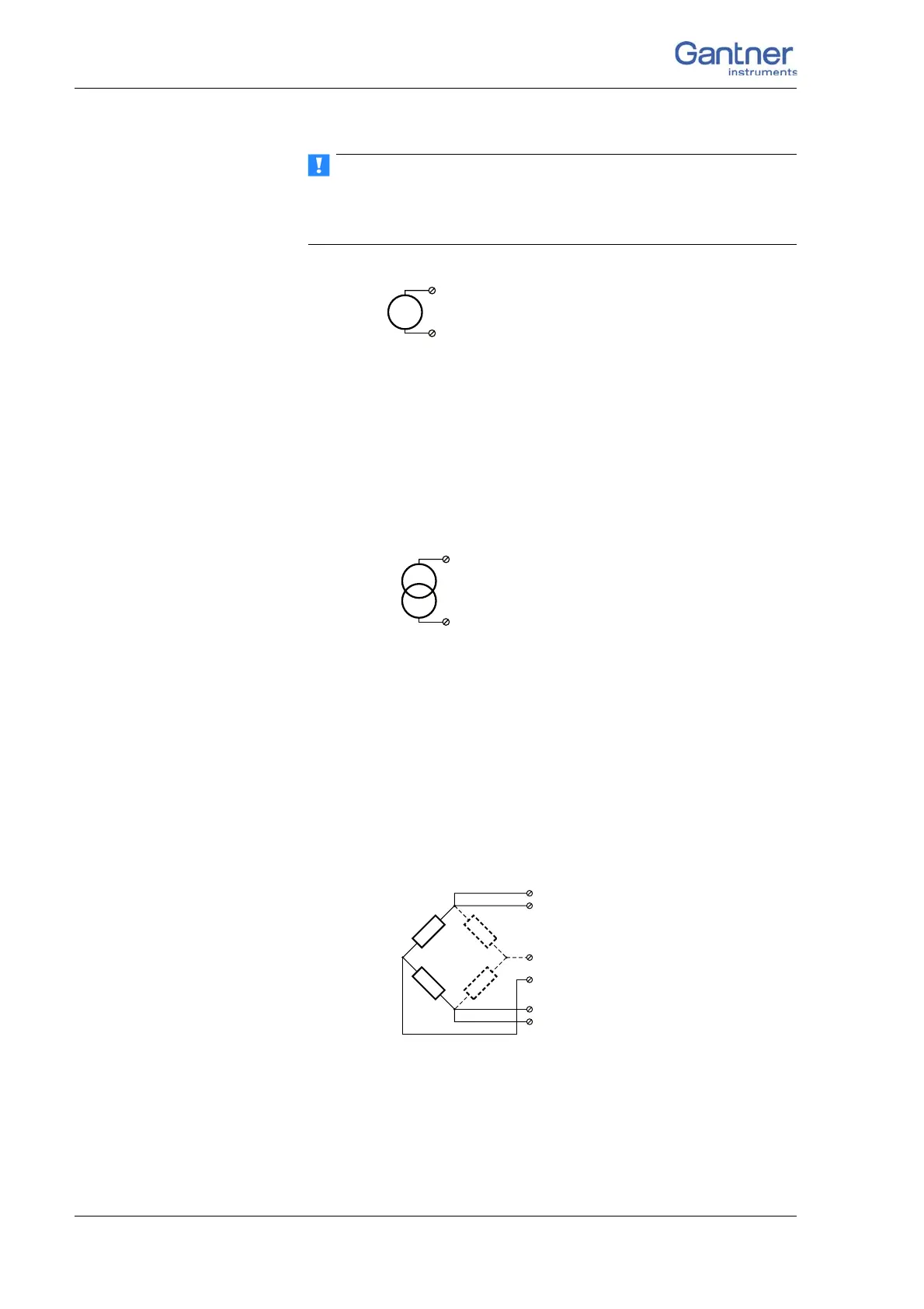
4.9.3 Full and half-bridge transducers
With (resistive) full bridges (strain-gauge full bridges) all connec-
tions are occupied. If the sensor has no sensing lea
ds, you specify
this during the module configuration (Type column). With half
bridges the side drawn in dashes and the connection 4 are omit-
ted.
The bridge excitation voltage is switched via software between
1 V, 2.5 V, 5 V and 10 V.
Fig. 4-31 A102, measurement with full and half bridges, Plug 2.

 Loading...