Q.series
Gantner Instruments GmbH
81
4 Connecting the modules → Q.bloxx A116: Connecting sensors
With the three-wire circuit the internal completion resistance is
used in this module to determine the voltage drop over the cable
and to correct the result accordingly. In this way not only can the
influence of the temperature on the cable (normal three-wire cir-
cuit) be compensated, but also the loss of sensitivity due to the
ca
ble resistance over a wide range.
4.18.3 Activating the shunt resistance
You can activate the shunt both via a variable and manually via a
button.
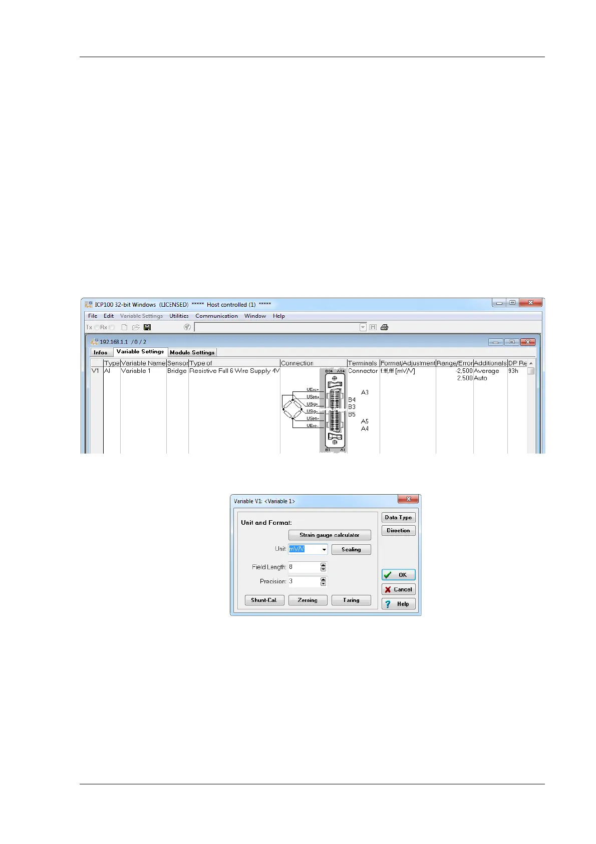
Open the module settings dialog(Fig. 4-76), activate the tab Vari-
ab
le definition and c
lick in the column Format/balance. The
dialog of Fig. 4-77 opens.
Fig. 4-76 Module configuration dialog.
Fig. 4-77 Dialog for format settings.

 Loading...